
User Manual


4
LAUNCH X-431 PAD
User's Manual
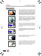
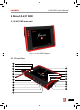
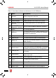
Table 2-1 formulates interfaces and indicators of X-431 PAD(front)
No. Name Descriptions
1
Communication
indicator
It flashes while X-431 PAD communicates with
DBScar diagnostic connector.
2 Bluetooth indicator It lights up while Bluetooth is activated.
3 Power indicator It lights up while X-431 PAD is on or in use.
4
DBScar diagnostic
connector
To communicate with X-431 PAD main unit.
5
Slot for DBScar
diagnostic connector
Only for housing DBScar diagnostic connector
6 Stylus For clicking operation
7 USB port
To connect USB devices. While extending X-431
PAD function, it is to be connected to Scopebox,
Sensorbox or batterybox.
8 VGA port To connect an external projector or monitor etc
9 Ethernet port To connect Ethernet cable for wired network
10 HDMI port
To connect an external projector or monitor with
HDMI interface
11 Borescope interface To connect an Borescope
12 Power interface To connect the included power adaptor
13 Touch screen
Color touch screen for displaying. On-screen
keyboard and handwriting input are supported.
14 Charging slot
Place X-431 PAD on the charging base (optional)
for charing.
15 Power button
Press once to turn it on; keep it pressed for a
while to turn it off.
16 Camera/video button for photographing or video recording
17
Screen capture
button
To capture the current screen
18 SD card slot To store SD card
19 Audio out port To connect earphone
20 Audio in port To connect audio device, such as amplier.