
User Manual

5
MAXIMUS
User's Manual
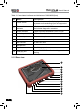
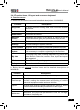
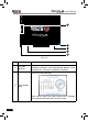
Table 2-2 formulates interfaces and indicators of MAXIMUS(rear)
No. Name Descriptions
11 Hook/stand
Use ngers to lift the hook up, then hang it on
the target object; To place it on a desk, install
it on the docking station directly or unfold the
hook as an stand to support MAXIMUS.
12 Battery cover
7400mAh lithium polymer battery is installed
below it.
13 Speakers
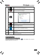
14 Camera lens To take photos or record video
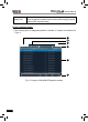
15 Power button
Press once to turn it on; keep it pressed for a
while to turn it off.
16
Slot for diagnostic
connector
Only for housing the diagnostic connector
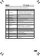
17 USB port
To connect USB devices. While extending
MAXIMUS function, it is to be connected to
Scopebox, Sensorbox or batterybox.
18 VGA port To connect an external projector or monitor etc
19 Ethernet port To connect Ethernet cable for wired network
20 HDMI port
To connect an external projector or monitor
with HDMI interface
21 Borescope interface To connect an Borescope
22 Power interface To connect the included power adaptor
23 Air vent
To exhaust heat to ensure a normal
temperature.