Version: V1.00.
MAXIMUS User's Manual FCC INFORMATION This device complies with Part 15 of the FCC Rules. Operation is subject to the following two conditions: 1. This device may not cause harmful interference, and 2. This device must accept any interference received, including interference that may cause undesired operation. Note: This equipment has been tested and found to comply with the limits for a Class B digital device, pursuant to part 15 of the FCC Rules.
MAXIMUS User's Manual All rights reserved! No part of this publication may be reproduced, stored in a retrieval system or transmitted, in any form or by any means of electronic, mechanical, photocopying and recording or otherwise, without the prior written permission of LAUNCH. This manual is designed only for the use of this unit. LAUNCH is not responsible for any use of this manual on the other units. The manual and all the samples herein can be changed without prior notice.
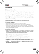
MAXIMUS User's Manual Precautions on Operating Vehicle’s ECU •• Do not disconnect the vehicle inner consumer when the ignition switch is on. High voltage transients may encounter at the moment of disconnecting, which may damage the sensors and the ECU. •• Protect the computer from magnetic object (such as wireless speaker) •• Do cut off the power supply of ECU system before welding on the vehicle. •• Pay more attention to the ECU and the sensors when the operation is next to them.
MAXIMUS User's Manual Safety Precautions •• Automotive batteries contain sulfuric acid that is harmful to skin. In operation, direct contact with the automotive batteries should be avoided. Pay attention not to splash the sulfuric acid into eyes. Keep the ignition sources away from the battery at all times. •• E n g i n e s p r o d u c e v a r i o u s p o i s o n o u s compounds (hydrocarbon, carbon monoxide, nitrogen oxides, etc,) which should be avoided.
MAXIMUS User's Manual Content 1 Foreword.......................................................................................................... 1 1.1 Product Introduction....................................................................................... 1 1.2 Product Features............................................................................................ 1 1.3 Product Functions.......................................................................................... 1 1.
MAXIMUS User's Manual 8 Update............................................................................................................ 53 8.1 Register........................................................................................................ 53 8.1.1 Register your information.................................................................... 53 8.1.2 Register your product.......................................................................... 55 8.2 Update................................
MAXIMUS User's Manual 1 Foreword 1.1 Product Introduction MAXIMUS is a new generation pad computer developed for automobile aftermarket. It is far more than a diagnostic scanner, it can also used as a pad computer, which enables users to enjoy all functions of Windows Embedded Standard 7 operating system. Built-in printer driver is equipped for printing once it is connected to an external printer via USB cable.
MAXIMUS User's Manual 1.4 Technical Specifications A. Main Unit Operating system: Windows Embedded Standard 7 Power: 12V input Battery: 7400mAh lithium polymer battery LCD: 9.7 inch touch screen CPU: dual-core 1.6GHz Memory: 2GB Hard disk: 16GB SSD Bluetooth: supports Bluetooth2.1 Wi-Fi: supports 802.11 b/g/n Camera Lens: 1.3 mega pixels C.
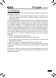
MAXIMUS User's Manual 2 About MAXIMUS 2.1 MAXIMUS main unit MAXIMUS main unit Docking station for MAXIMUS main unit Fig. 2-1 MAXIMUS Diagram 2.1.
MAXIMUS User's Manual Table 2-1 formulates interfaces and indicators of MAXIMUS(front) No. Name Descriptions 1 Touch screen Color touch screen for displaying. On-screen keyboard and handwriting input are supported. 2 Communication indicator It flashes while MAXIMUS communicates with the included diagnostic connector. 3 Power indicator It lights up while MAXIMUS is on or in use. 4 Audio in port To connect audio device, such as amplifier.
MAXIMUS User's Manual Table 2-2 formulates interfaces and indicators of MAXIMUS(rear) No. Name Descriptions 11 Hook/stand Use fingers to lift the hook up, then hang it on the target object; To place it on a desk, install it on the docking station directly or unfold the hook as an stand to support MAXIMUS. 12 Battery cover 7400mAh lithium polymer battery is installed below it.
MAXIMUS User's Manual 2.1.3 Docking Station 24 25 No. Name Descriptions 24 Charging port Align the charging port located on the bottom of the MAXIMUS with it and make sure the MAXIMUS main unit is firmly sitted on the docking station. 25 Jack for power Insert the power cord for docking station into this jack. cord 2.
MAXIMUS User's Manual Notes: *1. It keeps on when the connector is connected. *2. It lights up while the connector is communicating with your MAXIMUS. 2.3 MAXIMUS Accessory Checklist Common accessories for each MAXIMUS are same, but for different destinations, the accessories of MAXIMUS (such as diagnostic software, testing connectors) may vary. Please consult from the local agency or check the package list supplied with MAXIMUS together. Table 2-3: MAXIMUS common accessories and descriptions No.
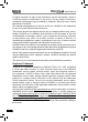
MAXIMUS User's Manual 8 SD card (optional) 1 9 OBD II extension cable 1 For extending memory 2.4 Getting to know MAXIMUS 2.4.1 Powering on MAXIMUS Press on the MAXIMUS to turn it on, the screen will begin to initialize, as shown in Fig.2-2. for 8 seconds can power it off. Doing so is not suggested, Note: Pressing please click "Exit system" on the main menu to turn it off. Fig. 2-2 After the system completes initializing, a message "Please register this unit with LAUNCH before continuing.
MAXIMUS User's Manual 2.4.2 Function items, UI layout and on-screen keyboard A. Function menus a. Below lists all function items and its detailed descriptions of MAXIMUS: Function Descriptions Diagnostic To check vehicle's working state, find out trouble location and cause. Camera To take photos or record video. Webbrowser To browse the internet. Message Center Feedback the trouble of the device or vehicle to us via E-mail and we will give you a professional reply in time.
MAXIMUS User's Manual BatteryTest The most advanced conductance testing technology in the world is applied to make vehicle battery and charging system testing safe, rapid and easy. B. User interface layout 1. The working area of diagnosis platform consists of 6 parts as indicated on Fig.2-4. A B C D E F Fig.
MAXIMUS User's Manual No. Name Notes This area shows the running tasks and the highlighted one is the currently displayed window. Click the area, a task list window will pop up, click the desired one to switch to the corresponding window. A Task status bar B Shortcut bar Provides shortcut to some commonly used functions, such as diagnosing, web browser and settings. Click it to toggle the function. Bluetooth: highlights while bluetooth is activated. Signal: displays the signal is strong or weak.
MAXIMUS User's Manual G H I J K Fig. 2-4 No. G Name Program shortcut Notes In case you choose to create a desktop icon while installing a software, it will automatically appear on the desktop once it has been installed successfully. Click to set time and date. H Time display area After setting, Date/Time under System tab in Settings will keep synchronized with it and vice verse.
MAXIMUS User's Manual Click it to set the input language. Click it to view the messages. Click it to define a power plan and view power status. I Network icon: Click it to configure network connection. Click it to adjust volume. Click it to return to MAXIMUS desktop. J Quick Launch bar Click the desired icon to launch the corresponding application. K Start Click it to select a desired program from the pull-down menu and execute it. C. On-screen keyboard 1.
MAXIMUS User's Manual Fig. 2-5 The layout of keyboard is possible to be different, but the operations of keys are same as that of PAD computer keyboard. 2. On MAXIMUS platform If you encounter a edit box or input area, click the blank area, a on-screen keyboard similar to Fig. 2-6 will appear. Fig. 2-6 Keys Name Functions Delete Place the cursor next to the character, and click this key to erase it. Hide keyboard Confirm Space Handwriting 14 Click it to hide on-screen keyboard.
MAXIMUS User's Manual 2.4.3 Settings It includes system settings and application setting. Language setting, Date/Time, Server Settings, Local Area Network, Brightness, Volume, Power Management, Screen Calibration, Wi-Fi and Third-party App Configuration are available in system setting, while application settings provide some settings related to applications. In main menu, click [ Settings] to enter setting interface, similar to Fig. 2-7. Fig. 2-7 1.
MAXIMUS User's Manual 2. Date/Time Setting This option can be used to set the system date, time and time zone. Click “Data/Time”, the screen will appear as Fig. 2-8. Fig. 2-8 A. Date setting In Fig. 2-8, click to switch to the previous/next month. Alternatively you can also click month or year directly and choose from the pull-down list (see Fig. 2-9). Then click on the desired date to set the date. Fig.
MAXIMUS User's Manual B. Time setting Click on the time display area, the cursor will blink, click the +/- button next to it to adjust it. Click [Show current time] to display the current time. C. Time zone setting Click [Timezone] in Fig. 2-8, a screen similar to 2-10 will appear. Fig. 2-10 Click the desired time zone, then click [Date] to switch to date setting screen, the time zone you have set will be displayed on the bottom of the screen and the system time varies with the time zone. 3.
MAXIMUS User's Manual 4. Local area network configuration Click “Local Area Network”, the screen will be shown as Fig. 2-12. Fig. 2-12 Operations: Automatically or manually obtain IP: A. You can select “Get the DNS address automatically” or “Use the following DNS address” to obtain IP address. B. You need to set DNS to manually input IP address.
MAXIMUS User's Manual In Fig. 2-13, drag the slider with stylus to adjust. 6. Adjust Volume This option is used to adjust the volume of speakers and microphone in play & record mode. Fig. 2-14 In Fig. 2-14, drag the slider with stylus to adjust the volume of speakers and microphone. Click “Record” to adjust the volume of microphone and microphone boost while recording. 7. Power Management This item enables you to have a general knowledge of current power information and set standby time.
MAXIMUS User's Manual Fig. 2-15 Fig. 2-16 8. Screen calibration This option lets you calibrate the touch screen. Click “Screen calibration”, “Please click the button to calibrate the touch screen” will be displayed on the screen. Click the “Screen Calibration” button to enter screen calibration interface. Fig. 2-17 Use the stylus to click the black dot, the dot will change in red and a progress reading will appear above it.
MAXIMUS User's Manual then one calibration has been finished. See Fig. 2-17. Fig. 2-18 Once all calibrations are made, the screen will display as Fig. 2-18 and the system will return to “Settings” interface automatically. 9. Wi-Fi This option allows you to configure Wi-Fi network. Click “Wi-Fi” and check the box next to “Close” to open it, the system will start searching wireless network. See Fig. 2-19.
MAXIMUS User's Manual Fig. 2-19 Choose one from the search result list to link. If the desired wireless router is encrypted, you can not connect to it until correct password is keyed in. Tick off the “Show Password” to confirm whether the password you input is correct or not. See Fig. 2-20. Fig. 2-20 Click “Manual Scanning” to scan manually, the screen will automatically refresh the search result.
MAXIMUS User's Manual Fig. 2-21 Click the edit box next to Network SSID, the on-screen keyboard will appear. Use the keyboard to input the wireless router name, and then choose one from the security type pull-down list. Where, Open means open network; WEP stands for unscured wireless network and WPE/WPA2 indicates the encrypted wireless network and you have to enter the correct password. After inputting, click “OK” to save your setting.
MAXIMUS User's Manual be displayed on the right window. See Fig. 2-23. If no third-party softwares are installed under Windows 7 operating system, the screen will appear blank. Fig. 2-23 Check the desired box before the software name, then click “Save” to save your configuration. The selected items will appear on the main menu of the diagnosis module. Once the installed softwares are shown out of the main menu, another icon will be appended next to the current one.
MAXIMUS User's Manual Fig. 2-24 12. User center This option allows you to set the relevant user information. Since this application is bound with Update Center, pay attention to the followings before setting this option: 1. Make sure the MAXIMUS is properly connected to the internet. If yes, go to Step 2. 2. On the desktop of MAXIMUS, click “Update Center”, and input CC number and password, then tick off the box “Remember Password” and click “Login in”.
MAXIMUS User's Manual A. Change Password This option enables you to modify the password that you set while registering. Input the old password and fill in “New Password” and “Confirm Password”, then click “Save” to revise it. B. Retrieve Password This option lets you take back the password if you forgot the registered password. Fig. 2-26 Click “Retrieve Password”, input your user name/ CC number/ E-mail, and click “Retrieve”, the system will feedback your password to your e-mail immediately. C.
MAXIMUS User's Manual 13. Audio test This option enables you to test the audio setting in Volume of System settings. Click “Record” to start recording; click “Stop” to stop recording. Click “Play” to play your recording.
MAXIMUS User's Manual 3 How to diagnose 3.1 Preparation and Connections 3.1.1 Preparation 111 Normal testing conditions •• Turn on the vehicle power supply. •• Vehicle battery voltage range should be 9-14V and working voltage of MAXIMUS is 12V. •• Throttle should be closed at its close position. •• Ignition timing and idle speed should be within specified range; water and transmission oil temperature are within normal working range (water temperature is 90-110℃ and transmission oil temperature is 50-80℃).
MAXIMUS User's Manual USB cable to the diagnostic connector, and other end to the USB port of MAXIMUS. No such connections are required for bluetooth diagnosing. 4. Choose one of the two ways to obtain power from: A. Cigarette lighter: remove the cigarette lighter, then connect one end of the cigarette lighter cable to vehicle’s cigaratte lighter hole, and the other end to the external power supply. B.
MAXIMUS User's Manual Vehicle Send diagnostic data to MAXIMUS via bluetooth or USB cable Diagnostic connector 3.2 Start diagnosing MAXIMUS can test a lot of vehicle make, models and systems which may continuously increase day by day. While MAXIMUS is online, the system will remind you of new released version automatically. To keep your MAXIMUS, please focus on prompt information and remember to download the latest diagnostic program in time.
MAXIMUS User's Manual Fig. 3-1 Descriptions for on-screen buttons: icons Name & functions Windows: to enter Windows 7 operating system. Desktop: to return to the main menu. Browser: click to open web browser. Settings: enter system settings interface. Module Info.: click to view the related inforation of current module. Print: print the test result. Before printing, a printer must be connected to the USB port of MAXIMUS via USB cable.
MAXIMUS User's Manual Take “Diagnose via Bluetooth” as example for demo. Click “Diagnose via Bluetooth”, the screen will be shown as Fig. 3-2. Fig. 3-2 A. Select Vehicle If the diagnostic connector be paired is the one you matched last time, click this option to enter vehicle make selection interface directly. There are 5 kinds of options are available, namely History, Common, European, American and Asian. Click “Asian”, the system will display all Asian vehicle makes. See Fig. 3-3. Fig.
MAXIMUS User's Manual Click the desired one (for example, DEMO) in Common to enter the software version selection screen. See Fig. 3-4. Fig.3-4 Choose one version, and click [OK], the system starts resetting and then validates the diagnostic connector. If ok, it will enter demo menu interface. Choose the desired one and start diagnosing demo. B. Search Bluetooth This option is used to search the bluetooth device. Click it to start searching, then choose the desired one from the result list to pair.
MAXIMUS User's Manual Fig. 3-5 After searching, a list of bluetooth devices (Bluetooth device’s name starts with Series No. of the diagnostic connector) will be shown on the screen. See Fig.3-6. Fig. 3-6 Click the desired bluetooth device, the system will display “Pairing bluetooth, please wait...”. If ok, “Pairing bluetooth succeed! Searching port, please wait...” will be shown on the screen, otherwise, “Pairing bluetooth failed!” will appear on the screen. Click [Back] to return to the previous screen.
MAXIMUS User's Manual 3.3 How to diagnose Click “DEMO” (in Common) on the vehicle selection menu, the screen will display the main menu for DEMO diagnosis program, as shown in Fig. 3-7. Fig. 3-7 Note: The operations for other models, series and systems are similar to “DEMO”. Please refer to the relevant operation interface for details. Here only take the “DEMO” for an example.
MAXIMUS User's Manual Fig. 3-8 Click [Engine] in Figure 3-8 (If there is more than one page of system menu, click to jump to the next page), the system message “Communication is initialized…” will appear on the screen. Note: The test method is similar for different systems, here take [Engine] for an example. After communicating, the interface will skip to the function menu of [Diagnose], as shown in Figure 3-9. Fig.
MAXIMUS User's Manual In Fig. 3-9, there are four functions of [Engine]: “Read trouble code”, “Clear trouble code”, “Read data stream” and “Special function”. 3.3.1 Read trouble code Click [Read trouble code] in Figure 3-9, MAXIMUS starts executing this function. After testing, results will appear on screen, as shown in Figure 3-10. Fig.3-10 Click to return to the previous screen. If the tested system has no DTCs, a message will appear on the screen, indicating that there are no DTCs in the system. 3.
MAXIMUS User's Manual Fig. 3-11 If trouble codes are cleared successfully, a prompt message will appear on the screen, as shown in Figure 3-11. If all trouble codes have been cleared, or there are no trouble codes, “No DTCs” will appear on the screen. Click to return to the function menu of diagnostic system. 3.3.3 Read datastream Click [Read datastream] as shown in Figure 3-9, you can read the running parameters. See Fig. 3-12. Fig.
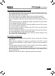
MAXIMUS User's Manual Click to select the desired datastream item (more datastream items can be chosen), then click , dynamic data of the selected datastream will appear on screen, as shown in Figure 3-13. Fig. 3-13 To view the dynamic waveform of the selected datastream, click [Record] ( and will become active) in Figure 3-14.
MAXIMUS User's Manual Fig. 3-14 If more datastream items are selected, click [Plot-2], [Plot-4], [Plot-6], [Plot-12] and [Combination] to switch to display in multi-view window mode. Fig. 3-15 and Fig. 3-16 represent the display effect of [Plot-4] and [Combination] respectively (Combination means to display the selected datastream items into one waveform with each datastream marking in different color for easy review and analysis). Fig. 3-15 Fig. 3-16 3.3.
MAXIMUS User's Manual Fig. 3-17 Note: We just take [1# injector] as an example to show how to set the special function. To detect whether [1# injector] works normally or not, click [1# injector], the screen will be shown as Fig. 3-18. Fig. 3-18 Note: If [1# injector] works abnormally, the system will fail to indicate that the part has some trouble.
MAXIMUS User's Manual 3.3.5 Driving record management View the recorded and saved datastreams and waveforms (To record, click [Record] on the running interface of datastreams). On vehicle selection menu, click in Fig. 3-19. Fig. 3-19 The system switches to Fig. 3-20, listing datastream information for different vehicles and records in different time. Select the one you want to view and click in Fig. 3-20. Fig.
MAXIMUS User's Manual Click , the screen will be shown as Fig. 3-21. To delete some test system record, click Click . to return to the previous screen. Fig. 3-21 To view datastream information, select the desired one and click , then the system will present you the recorded dynamic datastream information again.
MAXIMUS User's Manual 4 Webbrowser Browser is available on MAXIMUS, which helps you retrieve and search for information sources all the time. Click [Webbrowser] to enter. Fig. 4-1 In address bar, use the on-screen keyboard to input the Uniform Resource Identifier (URL) of the desired resource, and click to visit it. See Fig. 4-1. In search bar, input the desired information and click google search engine. Click to open a new blank page. Click to close the page.
MAXIMUS User's Manual Fig. 4-2 Click Favorites to bookmark the web pages so that the user can quickly return to them in future. Click to view and maintain the favorites.
MAXIMUS User's Manual 5 Camera MAXIMUS is equipped with a 1.3 mega pixel lens for your photographing and video recording. Pictures are taken in .jpg format and videos are recorded in .avi format. All pictures and videos are saved in relevant module folder in “My Data” where users can browse and replay it. Click [Camera], the screen will enter video recording interface as shown in Fig. 5-1. Fig. 5-1 In Camera mode, Drag Click scroll bar to adjust the screen size. to switch to video mode. See Fig. 5-4.
MAXIMUS User's Manual Fig. 5-2 View next picture Zoom out Return to the previous screen Zoom in Adjust picture to the suitable size Send the picture out via email Rotate the picture Rename the picture Fig.
MAXIMUS User's Manual In Video mode, Click to view all recorded video files. See Fig. 5-5. Click to start recording. While recording, drag size. Click Click to switch to camera mode. to exit the program. Fig.
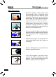
MAXIMUS User's Manual A B C D E F Fig. 5-5 Below are detailed descriptions on layout and functions on Fig. 5-4. Icon Name & Functions A Playback window B Playback progress bar: drag it directly to perform fast forward/fast reverse function. C Playback time D Return: return to the previous screen. E Playback control buttons: controls the progress of playback.
MAXIMUS User's Manual 6 Message Center MAXIMUS provides message center function, by which you can send E-mail to us once you come across any question or problem unresolved, and we will give you professional answer in time. To use this function, make sure that you have registered your product successfully and network is properly configured. 6.1 Read message Click [Message Center] on the main menu, the system will enter a screen similar to Fig. 6-1. Fig.
MAXIMUS User's Manual Click title or content edit box, the on-screen keyboard will appear automatically, use it to input or write down the title and contents by stylus manually. Button descriptions: [Attachment]: click to add an attachment. [ ]: send the message. [ ]: save a message that is not finished or will be sent later. [ ]: return to the previous screen. When a new message is finished, click [ ] to send. If the message is sent out successfully, a prompt message will pop up.
MAXIMUS User's Manual 7 J2534 Toolbox Flash programming has become a common and profitable procedure in the repair and service of today’s vehicles. As part of the 21st Century Tune-up, reprogramming is often the only solution for problems ranging from driveability and loss of power to poor fuel economy and emissions related issues. J2534box makes it easy.
MAXIMUS User's Manual 8 Update MAXIMUS provides quick and easy software update service, by which you can enjoy all update services including download and update the software. Note: Enter the update center, vehicle software which can be updated are default to be checked, you can click [Upgrade] to perform one-key update. You can also click [Opt] to select all or deselect all. 8.1 Register 8.1.1 Register your information To operate this device, you have to experience a product registration.
MAXIMUS User's Manual Fig. 8-2 Note: Before registering, please check you network configuration or Wi-Fi connection. After you registered successfully, the system will feedback a prompt message to you. If “Authenticate Email” is checked while registering, the system will also prompt you that you have bound Email successfully. Note: If Authenticate Email is checked while registering Email information, the system will send the confidential information to your Email immediately after registering successfully.
MAXIMUS User's Manual Fig. 8-3 Click [Login] to enter update center. 8.1.2 Register your product After registering your personal information, the screen will enter the product registration page. Fig. 8-4 Product SN is printed on the bottom of MAXIMUS.
MAXIMUS User's Manual (secret). Complete filling the information and click [Submit] to proceed to the next step. After registering your product, the system will enter update center. 8.2 Update While updating, make sure your network (wired or Wi-Fi) works properly, then click “One-click Update” to enter Fig. 8-5. Fig. 8-5 In Fig. 8-5, there are 3 options: Upgradable, Updated and History Diagnostic.
MAXIMUS User's Manual desired item, the checkbox will become to downloading, as shown on Fig. 8-6. , then click , the system will start Fig. 8-6 Click to pause the download. After download finishes, the system will install the softwar automatically. If “Installation succeed” appears, it indicates that installation has completed. If the network communication interrupts, software download will fail and “Installation failed” will be shown. In this case, please check the network and download it again.
MAXIMUS User's Manual 9 My data This option enables you to manage user data, including diagnostic data log, photos, videos. Moreover, you can perform browse, view, clear, and export etc. Data export is supported on all other options except Diagnostic software. In main menu of MAXIMUS, click [My data], the screen will be displayed as Fig. 9-1. Fig. 9-1 For details, please see the following Table 9-1.
MAXIMUS User's Manual Fig. 9-2 Click in the Name edit field, then the on-screen keyboard will appear. Input the desired name. Click the triangle and choose the destination path from the pulldown list. 9.2 Import data To import data from USB device into the MAXIMUS, click on the shortcut bar to export it. A import path dialog box will pop up, choose the desired path and click “OK”. A list of files will be listed on the screen, highlight the desired one and click to import it. 9.
MAXIMUS User's Manual Button Descriptions: Buttons Descriptions Refresh Refresh the current screen. List Arrange the files by list. Thumbnail Arrange the files in thumbnail mode. To select the itmes. Select all Select all items. Delete Delete the selected items. Select Export Export the select items. Cancel Selection Deselect the selected items. Return Return to the previous screen. 9.4 Review history diagnostic data Click “History Diagnostic Data” to enter the screen.
MAXIMUS User's Manual Select Return To select the itmes. Select all Select all items. Delete Delete the selected items. Export Export the select items. Cancel Selection Deselect the selected items. Return to the previous screen. 9.5 Clear Diagnostic software Click “Diagnostic Software”, a screen similar to Fig. 9-5 will appear: Fig. 9-5 Button Descriptions: Buttons Descriptions Enter the selected diagnostic software. Enter Clear Clear the selected software version.
MAXIMUS User's Manual 10 FAQ In process of operation of MAXIMUS, you may come across some questions, including the software, hardware, operation and something related to the vehicles. Read the user’s manual to get the answer if you have any question. If it can not be solved still, please note it down and contact our Customer Service Center for help. Here, we list some frequently asked questions and answers on using MAXIMUS. 10.
MAXIMUS User's Manual Q: Why MAXIMUS fails in communication with ECU? A: ECU does not respond. Please try to use the latest update tool to upgrade to the latest diagnostic program. 10.3 About system Q: Main screen blinks at the moment when engine ignition. A: It results from electromagnetic interference and this is normal phenomena. Q:Diagnose interrupted during diagnosing process. A: Caused by electromagnetic disturbing or poor connecting. Q: There is no response when communicating with on-board computer.
MAXIMUS User's Manual 5. Press ENTER to start recovering, and the screen will be shown as follows (Warning: Please DO NOT turn off the power while recovering!): 6.
MAXIMUS User's Manual 7. Press --> to restart your MAXIMUS. Note: After system recovery is complete, users need to connect MAXIMUS to internet and update it to the latest software version. 10.5 Other questions Q: How long is the standby time of battery? A: Recharge it correctly. In general, the charging time is about 6 hours for new machine. Once the charing icon disappears, it indicates it is fully charged. If standby time is set, it can last for about 7 hours.
MAXIMUS User's Manual Customer Service Department If you have any questions on the operation of the unit, please contact us: 1-877LAUNCH-9 Statement: LAUNCH reserves the rights to make any change to product designs and specifications without notice. The actual object may differ a little from the descriptions in the manual in physical appearance, color and configuration.