Quick Start Guide – OEM Installation SiI-SK63101 and SiI-SK63102 Quick Start Guide – OEM Installation
SiI-63101 and SiI63102 Quick Start Guide – OEM Installation Silicon Image, Inc. May 2012 Copyright Notice Copyright ©2012 Silicon Image, Inc. All rights reserved. The contents of these materials contain proprietary and confidential information (including trade secrets, copyright, and other Intellectual Property interests) of Silicon Image, Inc. or its affiliates.
SiI-63101 and SiI63102 Quick Start Guide – OEM Installation Silicon Image, Inc. Table of Contents Getting Started .............................................................................................................................................................. 2 SiI-SK63101 SiI-SK63102 module pair description.................................................................................................... 3 WirelessHD module/Adapter Connection Diagram.........................................
SiI-63101 and SiI63102 Quick Start Guide – OEM Installation Silicon Image, Inc. List of Figures Figure 1. SiI-SK63101 SiI-SK63102 module pair with supporting IO boards for testing ................................................. 3 Figure 2. SiI-SK63101 SiI-SK63102 module pair test setup ........................................................................................... 4 List of Tables Table 1. Transmitter and Receiver specifications...............................................................
SiI-63101 and SiI63102 Quick Start Guide – OEM Installation Silicon Image, Inc. Getting Started Follow the procedures described in this section to setup the SiI-SK63101 and SiI-63102 module pair: 1. Unpack the module pair. 2. Place the HDMI Video source and the HDMI video display in the same room at a reasonable distance apart (2 to 10m). 3. Connect the provided HDMI cable between the Tramsitter and the HDMI source output. 4.
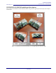
SiI-63101 and SiI63102 Quick Start Guide – OEM Installation Silicon Image, Inc. SiI-SK63101 SiI-SK63102 module pair description. Figure 2 shows the SiI-SK63101 and SiI-SK63102 modules along with the supporting IO board as part of the complete evaluation kit: Figure 1. SiI-SK63101 SiI-SK63102 module pair with supporting IO boards for testing ©2012 Silicon Image, Inc. All rights reserved.
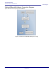
SiI-63101 and SiI63102 Quick Start Guide – OEM Installation Silicon Image, Inc. WirelessHD module/Adapter Connection Diagram. Figure 2 shows the basic setup using a WirelessHD link. Figure 2. SiI-SK63101 SiI-SK63102 module pair test setup 4 ©2012 Silicon Image, Inc. All rights reserved.
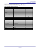
SiI-63101 and SiI63102 Quick Start Guide – OEM Installation Silicon Image, Inc. SiI-SK63101 & SiI-SK63102 Specifications: Table 1. Transmitter and Receiver specifications Parameter Value Notes Dimensions (in mm) X = 82, Y= 40, Z = 30 Each sides Operating temperature: 0C - 40C HDMI Receptacle Type A DC 3.3V Plug 2.5mm Mechanical Electrical Power Input VIN 3.3V DC, 2A Max input Voltage ripple <10% of VIN peak to peak Max power 2.5W (Max) Connected Power 2.
SiI-63101 and SiI63102 Quick Start Guide – OEM Installation Silicon Image, Inc. Interference Statement USA-Federal Communications Commission (FCC) This equipment has been tested and found to comply with the limits for a Class B digital device, pursuant to Part 15 of FCC Rules. These limits are designed to provide reasonable protection against harmful interference in a residential installation. This equipment generates, uses, and can radiate radio frequency energy.
SiI-63101 and SiI63102 Quick Start Guide – OEM Installation Silicon Image, Inc. L ‘ utilisation de ce dispositif est autorisée seulement aux conditions suivantes : (1) il ne doit pas produire de brouillage et (2) l’ utilisateur du dispositif doit étre prêt à accepter tout brouillage radioélectrique reçu, même si ce brouillage est susceptible de compromettre le fonctionnement du dispositif.
SiI-63101 and SiI63102 Quick Start Guide – OEM Installation Silicon Image, Inc. Marking by the symbol indicates that usage restrictions apply. CE RF Radiation Exposure Statement: Caution This equipment complies with European RF radiation exposure limits and is meant to be used as an Indoor device. The installer of this radio equipment must ensure that the minimum distance of 20cm shall be maintained between the antenna and the users of the host that this module is integrated into.
SiI-63101 and SiI63102 Quick Start Guide – OEM Installation Silicon Image, Inc. Marking/Labelling information Proposed Label and Location for SiI-SK63101 Receiver module Label Location SILICON IMAGE Model: SII-SK63101 FCC: UK2-SII-SK63101 IC: 6705A- SIISK63101 Front of Module Proposed Label and Location for Host Device installing SiI-SK63101 Receiver module This device contains Model: SII-SK63101 FCC: UK2-SII-SK63101 IC: 6705A- SIISK63101 ©2012 Silicon Image, Inc. All rights reserved.
SiI-63101 and SiI63102 Quick Start Guide – OEM Installation Silicon Image, Inc. Proposed Label and Location for SiI-SK63102 Transmitter module Label Location SILICON IMAGE Model: SII-SK63102 FCC: UK2-SII-SK63102 IC: 6705A- SIISK63102 Front of Module Proposed Label and Location for Host Device installing SiI-SK63102 Transmitter module This device contains Model: SII-SK63102 FCC: UK2-SII-SK63102 IC: 6705A- SIISK63102 10 ©2012 Silicon Image, Inc. All rights reserved.
SiI-63101 and SiI63102 Quick Start Guide – OEM Installation Silicon Image, Inc. References: Standards Documents Table 2 lists the abbreviations used in this document. Contact the responsible standards groups listed in Error! Reference source not found. for more information on these specifications. Table 2. Referenced Documents Abbreviation WiHD HDMI HCTS HDCP DVI E-EDID CEA-861-D EDDC Standards publication, organization, and date WirelessHD Specification, Version 1.
SiI-63101 and SiI63102 Quick Start Guide – OEM Installation Silicon Image, Inc. Disclaimers These materials are provided on an “AS IS” basis. Silicon Image, Inc.