
User's Manual

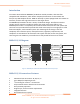


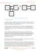
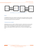

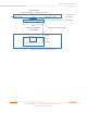
Table Of Contents
- Introduction
- MOD6212/13 Diagram
- MOD6212/13 transceiver Features
- 1
- 2
- 3
- 1
- 2
- 3
- MOD6212/13 Transceiver Module Dimensions
- 1
- 2
- 3
- 4
- MOD6212/13 Transceiver Module Pinout
- 1.
- 2.
- 3.
- 4.
- 5.
- MOD6212/13 Transceiver Module Connector
- MOD6212/13 Transceiver Module Functional description
- 1
- 2
- 3
- 4
- 5
- 6
- 7
- Modular approval for Lattice MOD6212/13 transmitter

Module Installation Guide
10 ©2017 SiBEAM, Inc., a Lattice Semiconductor company.
All rights reserved. CONFIDENTIAL
A
Module PCB
Host enclosure
(insulating)
Dimension A <= 3mm
26mm
10mm
10mm
Region with no metal permitted
Inward facing shielded side
MFC-VFBGA package
FRONT ELEVATION
PLAN ELEVATION
2.5mm
2.5mm
A
5mm
outward facing open side
2.5mm
direction of radiation
Figure 7: Module placement restrictions