
Installation & Assembly

PREPARATION
1. Shut o the power at the circuit breaker and remove existing xture, including the crossbar.
2. Carefully unpack your new xture and lay out all the parts on a clear area. Be careful not to lose any small parts necessary for installation.
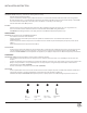
CONNECTING THE WIRES (Fig. 2)
3. Connect the xture wires with supply wires as shown in Fig. 2, making sure all wire connector(A1) are secured. If your outlet box has a
green or bare copper ground wire, connect the xture’s ground wire to it. Otherwise, connect the xture’s ground wire directly to the
mounting plate using the green screw provided. After all wires are connected, tuck them carefully inside the junction box.
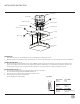
MOUNTING THE FIXTURE (Fig. 1)
4. Secure mounting plate to the junction Box using the junction box screws (B1) .
The side of the mounting plate marked “GND” must face out.
5. Place the canopy over the mounting plate and secure with screws.
6. Put the glass into the canopy and lock it with
allen screw (C1) by allen wrench (D1).
A1
C1
D1
B1
FIG.1
Junction Box
Connectors
Mounting Plate
Blue xture wire
Canopy
Screw
Glass
Allen screw
Allen wrench
Junction Box Screw
White Fixture Wire
Ground Wire
Fixture Wires
Black or
Smooth
Fixture Wires
White or
Ribbed
Fixture Wires
Bare wire
(Ground)
House Wires
Black
(Hot)
House Wires
White
(Neutral)
House Wires
Green or Bare Copper
(Ground)
Fig.2 Wiring
INSTALLATION INSTRUCTION