
Installation & Assembly

4
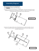
4.)
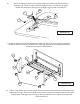
Illustration #3
P2
A
P7
P6
Place the Lock Rod (P7), as shown in Illustration #3, against the Left Leg (P2) and align holes.
Insert the Handle (P6) through the outside hole in the Left Leg (P2) and into the hole the the Lock
Rod (P7). Align the screw holes and secure with one Socket Screw (A).
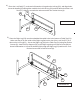
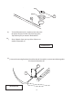
Place the Right Leg (P3) over the embedded threaded holes in the bottom of Table Top (P1).
Make sure the pin on the inside of the Right Leg fits into the slot of the Lock Rod (P7) as it
does on the Left Leg(P2). Secure the Right Leg (P3) to the Table Top (P1) using two Socket
Screws (B). Attach the Top Support (P5) to the Right Leg using one Socket Screw (B1) as
shown in Illustration #4. Insert the Handle (P6) through the Right Leg (P3) and into the Lock
Rod and secure with a Socket Screw (A).
Illustration #4
5.)
A
B
B1
P1
P3
P6