
Installation & Assembly

3
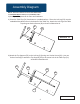
Assembly Diagram
Illustration # 1
1.)
2.)
R
EAD
T
HROUGH
I
NSTRUCTIONS
FROM
BEGINNING
TO
END
BEFORE
STARTING
TO
ASSEMBLE
UNIT
.
3.)
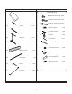
Identify and Separate all the Parts and Hardware.
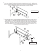
Illustration # 2
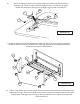
Place the Table Top (P1) face down on a padded surface. Place the Left Leg (P2) over the
embedded threaded inserts in the bottom of the Table Top. Attach the Left Leg to the Table
Top using two Socket Screws (B) as shown in Illustration #1.
P2
B
P1
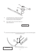
Attach the Top Support (P5) to the Left Leg (P2) using one Socket Screw (B1). Use one
Socket Screw (B) to attach the Top Support (P5) to the center hole in the Table Top (P1)
as shown in Illustration #2.
B
P1
P2
B1
P5