
Assembly And Installation Instructions
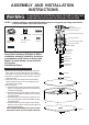

Turn on the power at fuse or circuit box
1x
2x
5. Pull out the source wires from the outlet box. Make wire connections using wire connectors as follows:
---Connect the black wire from the fixture to the black wire from the power source.
---Connect the white wire from the fixture to the white wire from the power source.
---Attach the fixture grounding wire to the mounting plate with the green grounding screw, and then connect it to the
house grounding wire with a wire connector.
Carefully put the wires back into the outlet box.
6. Attach the fixture canopy to the mounting plate by inserting the fixture mounting screws, and then secure it with two
ball nuts.
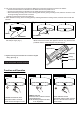
7. Push the pc diffuser into the shade
with oblique angel. (Fig.1)
8. Insert the sensor head into the hole of pc diffuser while the half of pc
diffuser reaches the shade, then tighten it with lock ring .Push the half
pc diffuser into the shade and place it in place (Fig.2).
9.Angled mounting recommended for a vaulted or angled
ceiling. (See Fig. 3)
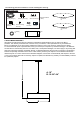
Function and Operation
TURNING LIGHTS ON, OFF
Wave hand under 4 inches of
sensor once to turn light on or off.
LOCK / UNLOCK LIGHT
Wave hand under 4 inches of sensor
within 0. 5 seconds twice to lock or
unlock sensor.
NOTE: Dimming ranges from 100%
to 5% brightness.
DIMMING LIGHTS
Hold hand under 4 inches of sensor
to adjust brightness.
ON-OFF
LOCK-UNLOCK
DIMMING
PC Diffuser
Shade
Fig.1
Lock Ring
Sensor Head
PC Diffuser
Fig.2
Fig. 3
Outlet Box
Support Brace
Canopy
Coupling Kit