
Product Manual
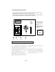

Prior to any measurement, you must "zero" the measuring mechanism or record the
readout , which must then be subtracted from the final measuring result.
To reset the mechanism to zero, use the zero setting wheel.
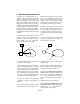
If you have a model L 30
your instrument is equipped with a rotatable tracer. Depress the arm tilt pin with your
right hand in order to lift the planimeter body off the measuring surface. Then, using
your left hand, set the mechanism to zero by means of the zero setting wheel.
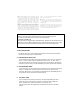
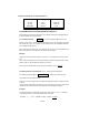
If this pointer points between two numbers, then the
lower of the two numbers is the second most signifi-
cant digit, except in one case. In this case, the marker
points between 0 and 9; then 9 rather than 0 is the
second most significant digit. If the pointer points
right at a number, then that number is the second
most significant figure, and the last two digits are
zero's.
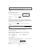
If the vernier pointer points between two numbers on
scale, "R", then it also points either at or between two
of the ten minor divisions separating the numbered
markers. If it points exactly at the third division for ex-
ample then the third most significant digit is a 3 and
the fourth is a 0. If it points between the third and
fourth minor division, then the third most significant
digit is a 3 and the fourth digit must be obtained
from the stationary vernier.
Now notice that one line on the stationary vernier,
"V", lines up best with one line on the measuring wheel
scale, "R". This line on the vernier represents the least
significant digit.
This digit is found by counting up to it from the 0
vernier line. For example, if the seventh line on the
vernier lines up best, then the last significant digit is a
seven .(as seen in the example on page 3)
Page 4
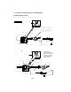
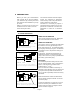
4. THE TRACER ARM
The length of the tracer arm is directly proportional to the measuring resolution
and the measuring range of the planimeter.
4.1 THE MEASURING RESOLUTION
is the smallest area increment which the instrument can record. It is expressed
as the "u" value. Model 10 and 20 planimeters have a fixed "u" value. The "u"
value of model 30 can be altered by changing its tracer arm length. The highest
resolution (=best accuracy) can be obtained by using the shortest arm extension.
4.2 THE MEASURING RANGE
is the area which can be covered by the instrument in one continuous tracing op-
eration. To obtain max. measuring range set the tracer arm to its longest
extension. (Mod. 30) If your instrument is equipped with an adjustable pole arm,
it can also be used to extend the measuring range.
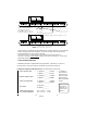
5. THE POLE ARM
does not affect the measuring resolution. Therefore adjustable pole arms
can be set to any length desired. (using the customary "Pole Outside the
figure" method.) The "pole inside method" is no longer used.
All Lasico pole arms are supplied with a pole weight for work on any table
surface.