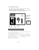
$ 1.50 d18\inst\l10inst INSTRUCTION MANUAL FOR MECHANICAL POLAR PLANIMETERS LASICO LOS ANGELES SCIENTIFIC INSTRUMENT CO. INC. 2451 RIVERSIDE DRIVE, LOS ANGELES, CA. - USA PHONE: (323) 662-2128 FAX : (323) 662-0904 E-Mail : lasico @ worldnet.att.net Website: www.lasico.
INSTRUCTIONS FOR THE USE OF LASICO MECHANICAL POLAR PLANIMETERS Thank you very much for selecting a Lasico Instrument. We hope it will serve you well for many years to come. Should you encounter any problems with the operation of your planimeter, please do not hesitate to contact us for assistance. CONTENTS CHAPTER PAGE 1. The Measuring Operation 1 2. 2.1 2.2 The Polar Planimeter and its Components Model Series 10 and 20 Model Series 30 2 2 2 3. The Measuring Mechanism 3 4. 4.1 4.
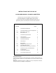
1. THE MEASURING OPERATION 1. Before any measurements are attempted, make sure that the measuring surface is suitable. It should not be very glossy, (photographs) too rough, mutilated, torn or patched up with adhesive tape. If the measuring surface is not quite suitable, cover it with a transparent sheet of tracing paper to minimize the problem. Make sure that the measuring table is reasonably flat and that both pole weight and planimeter body operate at the same elevation. 2.
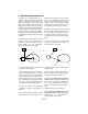
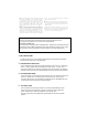
2. THE POLAR PLANIMETER AND ITS COMPONENTS 2.1 MODEL SERIES 10 AND 20 Note: Series 10 and 20 planimeters are identical except for tracer arm length. Shown: L 10 Pole Weight For smoothness of operation a teflon washer is attached Fig. 3 to the bottom of the lens tracer. It can be replaced by the user. Fixed Pole Arm (order Part No.
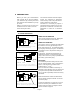
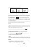
3. THE MEASURING MECHANISM The measuring mechanism consists of a counting dial, a measuring wheel with 100 divisions, and a vernier. The counting capacity is 9999 . When measuring large areas, it is important to closely watch the counting dial and to add 10 000 to the readout for each complete turn of the dial. Read Dial, Measuring Wheel and Vernier in this order: Dial = 2 M.Wheel (major)= 5 M.Wheel (minor) =4 Vernier =7 Result : 2547 7 VERNIER ( V ) 4 MEAS.
If this pointer points between two numbers, then the lower of the two numbers is the second most significant digit, except in one case. In this case, the marker points between 0 and 9; then 9 rather than 0 is the second most significant digit. If the pointer points right at a number, then that number is the second most significant figure, and the last two digits are zero's.
6. PREPARATIONS Before you start your measurements with a model 30 you need to optimize your instrument by choosing the tracer arm extension most suitable for your appli- cation. Owners of model series 10 and 20 instruments have no choice, since the tracer arm length is fixed. The readout results of mechanical planimeters are expressed in planimeter units and they need to be processed in order to obtain true area values.
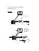
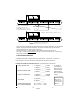
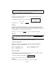
FOR 1:1 MEASUREMENTS THE TRACER ARM OF 13.98 These values are chosen for demo MODEL 30 CAN BE SET TO A PRECALIBRATED LENGTH purposes only. TRACER ARM SETTING SHOWN: 13.98 Fig. 9 the eighth line (counting to the left from the index) is aligned with a division line of the tracer arm. The tracer arm of your model 30 may be graduated in mm or half mm intervals. If you have half mm intervals, simply ignore the half mm divisions and set the arm length using only the mm lines.
Example Of A Model 10 / 20 Calibration Record Models u-Value (English) u-Value (Metric) 10 / 10A 20 / 20A 20M /20AM 0.01 in2 0.02 in2 0.015 in 2 0.0645 cm 2 0.129 cm 2 0.1 cm 2 6.3 DETERMINATION OF THE AREA MEASURING CONSTANT CA . After finishing the measuring operation, the readout result must be multiplied by CA in order to obtain the true area value. For 1:1 Measurements, CA = u ; i.e. the user simply multiplies his or her readout result by the u-value of the instrument in use.
Please note: You find the u-value entered into the formula in your Calibration Records. The u-value shown here was extracted from the example records on the previous page. However your u-values may be different . Example: Planimeter used: Model 30; Scale ratio : 1" = 660 feet; Long Arm Extension used; Results to be expressed in Acres. Sc2 x u The formula for determination of the Acre Constant : C A = ------------------- ; 43560 6602 x 0.02 Subsequently C A = ------------------- = 0.
7. INSTRUMENT TESTING AND RECALIBRATION Any area of known size can be used for instrument testing or recalibration. However since freehand tracing will inevitably introduce tracing errors, it is essential that multiple tracings are performed and averaged . 7. 1 Test Procedure We recommend to draw a 4 x 4 inch square if your instrument is calibrated for English (imperial) measuring units or a 10x10 cm square, if you use the metric system. Measure the area as outlined on page 1.
Determine u- value with formula: AT u = -------- ; N 16 u = ------ = 0.00927 in2 1725 where AT = size of of test area. Example : If your test area is a 4 x 4 inch square, and the readout result was 1725, then your new u-value is Use the same procedure to determine new u-values for the medium and long tracer arm. Record the new u-values. 8. THE COMPENSATING FEATURE To compensate for tracing errors, it is advisable to measure areas twice and to use the average of both results.