
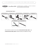
Installation Guide

PAGE 5
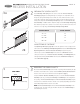
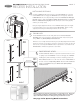
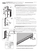
CHAIN LOCK
Position H-Chain Lock on the side wall jamb near the A-Screen Cassette
Assembly where it can engage the operating wand chain. Attach to the jamb
using a N-#8 x 1" (25mm) Phillips Panhead Screw.
When the screen is fully extended and being used, the Operating Wand should be
operated so that the screen fabric is taut in the opening. If necessary, the exposed
chain can be secured by the H-Chain Lock to help retain the screen fabric in the
B-Inside Rails as wind blows against the screen fabric.
5
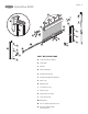
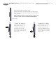
FOOT RELEASE LEVER
The K-Foot Release Lever is an optional feature that makes it easier
to slightly rotate the D-Pull Bar in order to disengage the L-Pull Bar
Locks [Fig 4C] without bending over. Before installing, position the
K-Foot Release Lever 12" to 20" from the end of the D-Pull Bar on
the side closest to the Operating Wand. Attach the K-Foot Release
Lever to the D-Pull Bar using two O-#6 x 3/8” (9mm) Phillips
Panhead Screws.
6
LEFT
RIGHT
B
L
C
B
L
C
D
K
O
B
E
4A
4B
4C
6
Windy conditions may affect the performance of a retractable screen. Retract the
screen in windy circumstances, during inclement weather, when not needed to
support immediate ventilation or during prolong periods when not used.
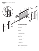
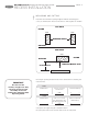
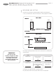
INSTALLING SIDE RAILS
Install the L-Pull Bar Locks at the bottom of each B-Inside Rail. Be sure that
the L-Pull Bar Locks can engage the D-Pull Bar as shown [Fig 4C]. Slide both
C-Outside Rails onto the tabs protruding from the F and G-Cassette End Caps
[Fig 4A]. Attach to jamb with N-#8x1” (25mm) Panhead Screws. Press B-Inside
Rails into C-Outside Rails [Fig 4B] with the shorter pile to the inside [Fig 4D]
until they are evenly seated.
Using the height adjustment wheels on the L-Pull Bar Locks, adjust the height
to the appropriate level so they easily engage the D-Pull Bar. When correctly
adjusted, the latching and unlatching should be smooth and easy.
4
Shorter Pile
4D
See page 10 for Operating Wand Instructions.
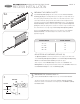
GRANDVUE 800 INSTALLATION INSTRUCTIONS
RECESS INSTALLATION