
Installation Guide

PAGE 4
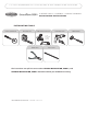
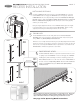
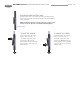
PREPARING THE SCREEN CASSETTE
Insert F-End Cap with Spring into the correct end of the A-Screen Cassette
Assembly [Fig 2A] (the assembly will only fit correctly in one end). Make sure to
line up the spring and bushing notches with one of the small slots in the center
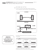
screen tube. Wind the spring clockwise the number of turns designated in the fol-
lowing chart and push the F-End Cap with Spring in place on the A-Screen Cas-
sette Assembly. A rubber mallet is helpful to fully seat the F-End Cap with Spring.
Note that the spring in the cassette is for tension only. You will need to raise and
lower the screen by using the G-End Cap with Operating Wand.
2
3
SIDE VIEW
HEAD
OUTSIDE
INSIDE
I-Recess Mount Clip
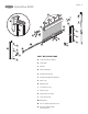
OPENING WIDTH
36”- 72”
73”-120”
120”-140”
140”-192”
SPRING TENSION
25
30
35
40
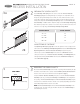
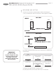
OPPOSITE END OF CARTRIDGE
Test Operating Wand (see page 10) for smooth operation. If it’s too tight, loosen
allen screw on the G-End Cap with Operating Wand. Insert the G-End Cap with
Operating Wand into A-Screen Cassette Assembly and push into place.
Slide one piece of the J-Weatherstrip into bottom slot of D-Pull Bar and the
other piece into the top of A-Screen Cassette Assembly. The M-Weight Bars are
already inserted inside the D-Pull Bar. Now insert the E-Pull Bar End Caps into
ends of D-Pull Bar [Fig 2B].
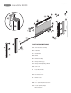
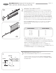
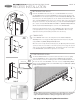
MOUNTING THE SCREEN CASSETTE
Mount the I-Recess Mount Clips to the inside of opening. When installed, the clips
should be centered above the cassette. Install a N-#8x1” (25mm) Panhead Screw
into the center of the slot to allow front to back adjustment [Fig 3].
Snap the A-Screen Cassette Assembly into place. Secure the A-Screen Cassette
Assembly in place by screwing the F-End Cap and G-End Cap to the side jamb of
the opening. The I-Recess Mount Clips and A-Screen Cassette Assembly may be
reversed to face toward the inside or outside of an opening depending upon which
side the Operating Wand needs to be accessible.
NOTE: the I-Recess Mount Clips lower the A-Screen Cassette Assembly in the
opening by 1/4”. The same 1/4” gap should be left above the F & G-End Caps to
avoid bowing the cassette.
D
A
J
J
E
E
M
F
A
2A
2B
3
GRANDVUE 800 INSTALLATION INSTRUCTIONS
RECESS INSTALLATION