
Installation Guide

1-1/8” – 1-1/2”
1-1/2” – 1-5/8”
1-5/8” – 2”
202220711CHW
REVISED 4-1-2020
Mortised Instructions
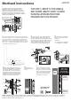
1.
Verify that the flat edge of the latch bolt is facing
towards the exterior of door, aligned for a left or
right position corresponding with your door’s hinge
orientation. It may be necessary to remove the mortise
plate from the assembly for reversing the bolt. Rotate
the latch bolt and reposition the mortise plate, attaching
with the latch assembly screws.
OUTSIDE:
Flat Edge
Latch Assembly Screw
Mortise Plate
Latch Assembly
Latch Bolt
Right Hinge
Position
Left Hinge
Position
3a.
Assemble the Exterior handle and bushing through
the exterior trim plate. From the back of the trim
plate, place the flat washer onto the handle post and
slide the “D” clip over the washer. Make sure the “D”
clip is positioned opening down as shown and then
insert the spindle into the handle. Tighten the set
screw with the hex key (Allen Wrench) provided.
3b.
Insert key and rotate the deadbolt
spindle so the proper letter code is
facing up.
Letter Code:
“R” = right hinge door installations
“L” = left hinge door installations
3d.
Attach the mortise
body using two mortise
screws.
“D” Clip
Spindle
Flat Washer
“D” Clip
Flat Washer
Exterior Handle
Bushing
Hex Key
Set Screw
R
L
Letter Code
3c.
Install the handle assembly as shown. Make
certain the deadbolt spindle is correctly oriented
as described in 3b. Align the inside turn knob
in the upright position. From the inside of the
door, align the trim plates and attach using two
trim plate screws. Hold the handles together
and tighten the set screw on the interior handle
using the hex key (Allen Wrench) provided.
Set Screw
Hex Key
EXTERIOR
Handle Assembly
KEY
may be necessary
to turn spindle
Interior Handle
Bushing
Trim Plate Screw
Interior
Trim Plate
Turn Knob
Mortise
Screw
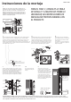
Short Strike Screw
#8 x 7/16" Qty. 2
#8 FLAT HEAD
STRIKE SCREWS
#8 FLAT HEAD
STRIKE SCREWS
MOUNTING
FRAME
SCREWS LOCATED AT
REAR OF SLOT IN STRIKE
STRIKE LOCATED AGAINST
FRONT OF MOUNTING FRAME AREA
4.
Open the door and position the strike
plate on the mounting frame. Slide the
strike plate to the edge of the mounting
frame as shown. Install two #8 Flat head
screws, test lock operation and adjust
strike as needed. Check that the latch
and deadbolt operate properly.
2.
Trim the flat key cylinder spindle to the length needed using the above
chart. For doors that are 1-1/8” to 1-1/2” thick, the square spindle will
need to be inserted into the outside handle to the 3rd line in step 3a.
For doors that are 1-1/2” 1-5/8” thick, the square spindle will need to
be inserted into the outside handle to the 2nd line in step 3a. For doors
that are 1-5/8” – 2” thick, the spindle will need to be inserted into the
outside handle to the first line in step 3a.
LARSON Limited Warranty - This product is warranted to be free of defects in material and workmanship for a period of one year from the date of original retail
purchase. Performance under this warranty requires notification by the owner to LARSON Manufacturing and proof of purchase. For warranty or installation
questions call 888-483-3768 or visit larsondoors.com.
FOR STEP 2, REFER TO THE SPINDLE
AND SCREW LENGTH CHART LOCATED
IN INSTALLATION INSTRUCTIONS
PROVIDED WITH THE PRODUCT.