XPress-Pro SW 92000 User Guide Part Number 900-505 Revision A May 2007
Copyright & Trademark © 2005, Lantronix. All rights reserved. No part of the contents of this book may be transmitted or reproduced in any form or by any means without the written permission of Lantronix. Printed in the United States of America. Ethernet is a trademark of XEROX Corporation. UNIX is a registered trademark of The Open Group. Windows 95, Windows 98, Windows 2000, and Windows NT are trademarks of Microsoft Corp. Netscape is a trademark of Netscape Communications Corporation.
Contents 1: Preface 4 Plug-and-Play Solution _______________________________________________ 4 2: Product Overview 5 Hardened Compact Switch ____________________________________________ 5 Package Contents ___________________________________________________ 5 Product Highlights ___________________________________________________ 5 Front Panel Display __________________________________________________ 6 Physical Ports ______________________________________________________ 7 Connectivity _________________
1: Preface A member of the growing family of rugged switches, this switch addresses a need for a smaller switch. This switch provides an affordable solution for rugged and outdoor environment, transportation road-side cabinet, industrial floor shop, multitenant dwellings or Fiber To The Home (FTTH) applications. Capable of operating at temperature extremes of -34°C to +74°C, this is the switch of choice for harsh environments constrained by space.
2: Product Overview Hardened Compact Switch Package Contents When you unpack the product package, you shall find the items listed below. Please inspect the contents, and report any apparent damage or missing items immediately to your authorized reseller. This Switch User’s Manual External power adapter & Power Cord (Optional) Product Highlights Meets NEMA TS2 Environmental requirements such as temperature, shock, and vibration for traffic control equipment.
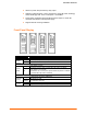
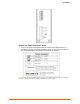
2:Product Overview Alarms for power and port failure by relay output. Operating voltage and Max. current consumption: 12VDC @ 0.99A, 24VDC @ 0.55A, 48VDC @ 0.39A. Power consumption: 18.72W Max. Power Supply: Redundant DC Terminal Block power inputs or 12VDC DC JACK with 124-240VAC external power supply. Supports Din-rail mounting installation. Front Panel Display LED POWER PWR1 PWR2 (Green) FAULT FAULT (Red) State Indication Steady Switch is properly connected to power and turned on.
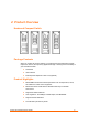
2:Product Overview Physical Ports This switch provides: Eight 10/100BaseTX ports Eight 10/100BaseTX ports + one 100BaseFX port Six 10/100BaseTX ports + two 100BaseFX ports Four 10/100BaseTX ports + four 100BaseFX ports Connectivity RJ-45 connectors SC, ST, VF-45 or MT-RJ connector on 100BaseFX fiber port.
3: Installation This chapter gives step-by-step instructions about how to install the switch: Selecting a Site for the Switch As with any electric device, you should place the switch where it will not be subjected to extreme temperatures, humidity, or electromagnetic interference. Specifically, the site you select should meet the following requirements: The ambient temperature should be between -34 to 74 degrees Celsius. The relative humidity should be less than 95 percent, non-condensing.
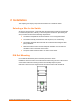
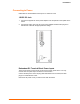
3:Installation Connecting to Power Redundant DC Terminal Block Power Inputs or 12VDC DC Jack: 12VDC DC Jack 1. Connect the supplied AC to DC power adapter to the receptacle on the topside of the switch. 2. Connect the power cord to the AC to DC power adapter and attach the plug into a standard AC outlet with the appropriate AC voltage. Redundant DC Terminal Block Power Inputs There are two pairs of power inputs can be used to power up this device.
3:Installation Alarms for Power and Port Failure 1. There are two pins on the terminal block are used for power failure detection. It provides the normally closed output when the power source is active. Use this as a dry contact application to send a signal for power failure detection. Note: The relay output is normal open position when there is no power to the switch. Please do not connect any power source to this terminal to prevent the shortage to your power supply.
3:Installation Connecting to Your Network Cable Type & Length It is necessary to follow the cable specifications below when connecting the switch to your network. Use appropriate cables that meet your speed and cabling requirements. Cable Specifications Speed Connector 10BaseT 100BaseTX 100BaseFX 100BaseFX RJ-45 RJ-45 SC, ST, VF-45, MT-RJ SC Port Speed Half/Full Duplex Cable Max. Distance 10/20 Mbps 100/200 Mbps 100/200 Mbps 100/200 Mbps 2-pair UTP/STP Cat. 3, 4, 5 2-pair UTP/STP Cat.
A: Specifications Specification Description Hardened Compact Switch 10/100BaseT/TX auto-negotiating ports with RJ-45 connectors, 100BaseFX fiber ports IEEE 802.3 10BaseT IEEE 802.
B: Connector Pinouts Pin arrangement of RJ-45 connectors The following table lists the pinout of 10/100BaseT/TX ports.