XPort™ User Guide Part Number 900-270 Revision E August 2004
Copyright and Trademark © 2004, Lantronix. All rights reserved. No part of the contents of this book may be transmitted or reproduced in any form or by any means without the written permission of Lantronix. Printed in the United States of America. XPort, with its patent-pending technology, is a trademark of Lantronix. Ethernet is a trademark of XEROX Corporation. UNIX is a registered trademark of The Open Group.
Disclaimer and Revisions Operation of this equipment in a residential area is likely to cause interference, in which case the user, at his or her own expense, will be required to take whatever measures may be required to correct the interference. Changes or modifications to this device not explicitly approved by Lantronix will void the user's authority to operate this device.
Contents 1: Using This Guide 7 Purpose and Audience________________________________________________ 7 Chapter Summary ___________________________________________________ 7 Additional Documentation _____________________________________________ 8 2: Introduction 9 Capabilities ________________________________________________________ 9 Applications ________________________________________________________ 9 Protocol Support ___________________________________________________ 10 Addresses and Port Numbers _
Contents Using a Telnet Connection ________________________________________________ 21 Using the Serial Port _____________________________________________________ 22 Server Configuration (Network Configuration)_____________________________ 24 IP Address_____________________________________________________________ 24 Set Gateway IP Address __________________________________________________ 24 Netmask: Number of Bits for Host Part_______________________________________ 24 Change Telnet Configuration Passwor
Contents Disable TFTP Firmware Upgrade __________________________________________ 41 Disable Port 77FE (Hex) _________________________________________________ 41 Disable Web Server _____________________________________________________ 41 Disable ECHO Ports_____________________________________________________ 41 Enable Encryption ______________________________________________________ 41 Encryption Tutorial ______________________________________________________ 42 Enable Enhanced Password ___________________
1: Using This Guide Purpose and Audience This guide provides the information needed to configure, use and update the XPort™ and is intended for software developers and system integrators who are embedding the XPort in their designs. The information in this guide is relevant to XPort with firmware version 1.5 and higher. Note: This document covers XPort™ Device Server versions XP1001000-01, XP1001000-03, and XP1004000-03 (XPort-485).
1: Using This Guide Additional Documentation The following guides are available on the product CD and the Lantronix web site (www.lantronix.com). XPort Quick Start Provides the steps for getting the XPort evaluation board up and running. XPort Integration Guide Provides information about the XPort hardware, testing the XPort using the evaluation board, and integrating the XPort into your product.
2: Introduction This chapter summarizes the XPort device server’s features and basic information needed before getting started. Capabilities The XPort device server has the following capabilities: Connects devices through a TCP data channel or through a Telnet connection to computers or to another device server. The XPort also supports UDP datagrams. Contains a web [HTTP] server allowing presentation of custom content and easy configuration through the browser.
2: Introduction Protocol Support The XPort device server uses the Internet Protocol (IP) for network communications. It uses the Transmission Control Protocol (TCP) to assure that no data is lost or duplicated, and that everything sent to the connection arrives correctly at the target. Other supported protocols include: ARP, UDP, TCP, ICMP, Telnet, TFTP, AutoIP, DHCP, HTTP, and SNMP for network communications and management. TCP, UDP, and Telnet for connections to the serial port.
2: Introduction Assigning an IP Address For the unit to operate correctly on a network, it must have a unique IP address on the network. There are three basic methods for logging into the device server and assigning the IP address: DHCP: By default, Dynamic Host Configuration Protocol (DHCP) is enabled on the device server. DHCP allows a DHCP server to automatically assign an IP address to the device server. If you use DHCP, the device server is assigned a new IP address each time it boots.
3: Getting Started This chapter covers the steps for getting the XPort device server online and working. Required Information Hardware Address You need to know the unit’s hardware address (also known as MAC address), which is on the product label. It is in the format: 00-20-4a-XX-XX-XX, where the XXs are unique numbers assigned to the product. Hardware Address: 00-20-4a-_____-_____-_____ IP Address The XPort must have a unique IP address on the network.
3: Getting Started a) Click the Start button on the Task Bar and select Run. b) Enter your CD drive letter, colon, backslash, Launch.exe (e.g., D:\Launch.exe). 3. Click the DeviceInstaller button. The installation wizard window displays. 4. Respond to the installation wizard prompts. Note: For more information about Device Installer, see the DeviceInstaller User Guide on the product CD and the DeviceInstaller online help. Assigning an IP Address The unit’s IP address is normally set to 0.0.0.
3: Getting Started Using Web-Manager to Configure the Unit You must configure the unit so that it can communicate on a network with your serial device. For example, you must set the way the unit will respond to serial and network traffic, how it will handle serial packets, and when to start or close a connection. The unit’s configuration is stored in nonvolatile memory and is retained without power. You can change the configuration at any time.
3: Getting Started On the left side of the screen, Web-Manager has the following menu options (buttons): Unit Configuration Server Properties Port Properties Factory Settings1 Update Settings Select Channel 4. Use the menu to navigate to subpages for the configuration of server settings. 5. When finished, click the Update Settings button to save the settings. Notes: The next chapter, 4:Using Setup Mode, explains the configuration settings in detail.
3: Getting Started This page displays the current Server Configuration and the Port Configuration settings. Note: The following examples represent typical web pages. See the Lantronix web site for the latest version. Server Properties Click the Server Properties button to display the following page: Change the server properties by editing any of the fields. Holding the cursor over a field displays a Help message for that field.
3: Getting Started characters. (An enhanced password setting of 16 characters is available under Security Settings on the Telnet Setup Mode window.) Note: You do not need a password to access the Setup Mode window via a serial connection. Port Properties Click the Port Properties button to display the following page: Edit the following fields as necessary: Serial Protocol RS232 Note: RS-232 is the only available option for XPort Device Server versions XP1001000-01 & XP1001000-03.
3: Getting Started the baud rates 460800 and 921600 bps (see High CPU Performance mode on page 39) Character Size 8, 7 Parity None, Even, Odd Stop Bit 1,2 Flow Control None, XON/XOFF, XON/XOFF Pass Characters to Host, CTS/RTS (Hardware) Connect Mode Settings UDP Datagram Mode Enable, Disable UDP Datagram Type User Selectable Incoming Connection Accept unconditional, Accept incoming/DTR, Never accept incoming Response Nothing (quiet), Character Response Startup No Active Connection Startup
3: Getting Started On Active Connection Enable, Disable On Passive Connection Enable, Disable At Time To Disconnect Enable, Disable Packing Algorithm Packing Algorithm Enable, Disable Idle Time Packing Interval 12 ms, Interval 52 ms, Interval 250 ms, Interval 5000 ms Trailing Characters None, One, Two Send Immediate After Sendchars Enable, Disable Sendchar Define2-Byte Sequence Enable, Disable Send Character 01 User selectable Send Character 02 User selectable Additional Settings Disc
3: Getting Started Factory Settings Click the Factory Settings button to set the device server back to the factory default settings. For details see page Factory Defaults on page 43. Update Settings Click the Update Settings button to send all changed settings to the device server.
4: Using Setup Mode for Configuration You must configure the unit so that it can communicate on a network with your serial device. You can configure it using a web browser, as described in 3:Getting Started, or using the following procedures locally or remotely: Use a Telnet connection to configure the unit over the network. Use a terminal or terminal emulation program to access the serial port locally.
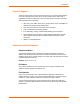
4: Using Setup Mode for Configuration 3. To enter the Setup Mode, press Enter within 5 seconds. The configuration settings display, followed by the setup menu options. Figure 4-2 Setup Menu Options Change Setup: 0 Server configuration 1 Channel 1 configuration 3 E-mail settings 5 Expert settings 6 Security 7 Factory defaults 8 Exit without save 9 Save and exit ? Your choice 4. Select an option on the menu by entering the number of the option in the Your choice ? field and pressing Enter. 5.
4: Using Setup Mode for Configuration Figure 4-3 Setup Mode Configuration Parameters XPort™ User Guide 23
4: Using Setup Mode for Configuration Server Configuration (Network Configuration) The unit’s basic network parameters display when you select Server configuration (option 0). The IP Address, Set Gateway IP Address, and Netmask fields display the current values. Figure 4-4. Server Configuration Parameters IP Address : (000) .(000) .(000) .
4: Using Setup Mode for Configuration DHCP Name If a DHCP server has automatically assigned the IP address and network settings, you can discover the unit by using the DeviceInstaller network search feature. There are three methods for assigning DHCP names to the unit. Default DHCP Name: If you do not change the DHCP name, and you are using an IP of 0.0.0.0, then the DHCP name defaults to CXXXXXX (XXXXXX is the last 6 digits of the MAC address shown on the label on the bottom/side of the unit).
4: Using Setup Mode for Configuration 4800, 9600 (default), 19200, 38400, 57600, 115200, and 230400 bits per second. XPort-03 and greater units also support high-performance baud rates of 460800, and 921600 bits per second (see Expert Settings on page 38). I/F (Interface) Mode The Interface (I/F) Mode is a bit-coded byte entered in hexadecimal notation. Table 4-2.
4: Using Setup Mode for Configuration Flow Flow control sets the local handshaking method for stopping serial input/output. Use the following table to select flow control options: Table 4-5. Flow Control Options Flow Control Option Hex No flow control 00 XON/XOFF flow control 01 Hardware handshake with RTS/CTS lines 02 XON/XOFF pass characters to host 05 Port Number The setting represents the source port number in TCP connections.
4: Using Setup Mode for Configuration Connect Mode Connect Mode defines how the unit makes a connection, and how it reacts to incoming connections over the network. Enter Connect Mode options in hexadecimal notation. Table 4-7.
4: Using Setup Mode for Configuration Response Character Response A single character is transmitted to the serial port when there is a change in connection state: C = connected, D = disconnected, N = host unreachable. This option is overridden when the Active Start Modem Mode or Active Start Host List is in effect. Default setting is Nothing (quiet). No Active Startup Does not attempt to initiate a connection under any circumstance. Default setting.
4: Using Setup Mode for Configuration Command String Result if remote IP is 129.1.2.3 and remote port is 1234 C0.0.0.0/0 Connects to 129.1.28.10, port 12; enters Monitor Mode Autostart (Automatic Connection) If you enable autostart, the unit automatically connects to the remote IP address and remote port specified when the firmware starts. Hostlist If you enable this option, the device server scrolls through the hostlist until it connects to a device listed in the hostlist table.
4: Using Setup Mode for Configuration DisConnTime (00:00) ?: SendChar 1 (00) ? SendChar 2 (00) ? To enable the hostlist: 1. Enter a Connect Mode of 0x20 (2X), where X is any digit. The menu shows you a list of current entries already defined in the product. 2. To delete, modify, or add an entry, select Yes. If you enter an IP address of 0.0.0.0, that entry and all others after it are deleted. 3. After completing the hostlist, repeat the previous step if necessary to edit the hostlist again. 4.
4: Using Setup Mode for Configuration Full Verbose The unit echoes modem commands and responds to a command with a message string shown in the table below. 1-Character Response The unit echoes modem commands and responds to a command with a single character response. Table 4-11. Modem Mode Messages Message Meaning Full Verbose OK Command was executed without error. CONNECT A network connection has been established. NO CARRIER A network connection has been closed. RING n.n.n.n.
4: Using Setup Mode for Configuration The character string ATH is received, terminated with a carriage return. The unit responds affirmatively according to the selected echo/response mode and drops the network connection. The serial interface reverts to accepting command strings. If this sequence is not followed, the unit remains in data transfer mode. Table 4-12. Modem Mode Commands Modem Mode Command Function ATDTx.x.x.x,pppp or ATDTx.x.x.x/pppp Makes a connection to an IP address (x.x.x.
4: Using Setup Mode for Configuration Note: To connect an ASCII terminal to a host using the unit for login purposes, use the remote port number 23 (Internet standard port number for Telnet services). DisConnMode This setting determines the conditions under which the unit will cause a network connection to terminate. Note: In DisConnMode (Disconnect Mode), DTR drop either drops the connection or is ignored. Table 4-13.
4: Using Setup Mode for Configuration Function 7 Clear when the network connection to or from the device is disconnected 6 5 4 3 2 1 0 1 Output Buffer (Network to Serial) Clear with a connection that is initiated from the device to the network 1 Clear with a connection initiated from the network to the device 1 Clear when the network connection to or from the device is disconnected 1 Alternate Packing Algorithm (Pack Control) Enable 1 Pack Control Two firmware-selectable packing algorith
4: Using Setup Mode for Configuration Packing Interval: Packing Interval defines how long the unit should wait before sending accumulated characters. This wait period is between successive network segments containing data. For alternate packing, the default interval is 12 ms. Trailing Characters: In some applications, CRC, Checksum, or other trailing characters follow the end-of-sequence character; this option helps to adapt frame transmission to the frame boundary.
4: Using Setup Mode for Configuration E-mail Settings Note: You can change these settings via Telnet or serial connections only, not on the Web-Manager. To configure e-mail settings via DeviceInstaller, see E-mail Notification in the DeviceInstaller User Guide on the CD. The unit can send an e-mail to multiple recipients when a specific trigger event occurs. There are three separate triggers, based on any combination of the configurable pins (PIO) when selected as user I/O functions.
4: Using Setup Mode for Configuration Trigger Setup A trigger event can occur when the unit receives two bytes of a specified sequence on the serial port, or because of a specified combination of conditions on the configurable pins. If the serial sequence is set to 00,00, the trigger is disabled. At the Serial Sequence prompt, enter the ASCII Hex value. Example: A two byte sequence of 12 would be 0x31, 0x32. If the configurable pins are all set to X (Don’t Care), then they are disabled.
4: Using Setup Mode for Configuration TCP Keepalive time in seconds This option allows you to change how many seconds the unit will wait during a silent connection before attempting to see if the currently connected network device is still on the network. If the unit then gets no response, it drops that connection. ARP Cache timeout in seconds Whenever the unit communicates with another device on the network, it adds an entry into its ARP table.
4: Using Setup Mode for Configuration configure one of the configurable pins to RS485_TXEN. To change the configurable pins’ settings, use DeviceInstaller or send setup records to port 77FE. Security Settings You can change security settings via Telnet or serial connections only, not on the Web-Manager. We recommend that you set security over the dedicated network or over the serial setup. If you set parameters over the network (Telnet 9999), someone else could capture these settings.
4: Using Setup Mode for Configuration Disable TFTP Firmware Upgrade This setting defaults to the N (No) option. The Y (Yes) option disables the use of TFTP to perform network firmware upgrades. With this option, you can download firmware upgrades over the serial port using DeviceInstaller’s Recover Firmware procedure. (See Recovering the Firmware Using the Serial Port on page 51.
4: Using Setup Mode for Configuration Encryption only applies to the port selected for tunneling (default 10001), regardless of whether you are using TCP or UDP. Generally, one of two situations applies. Encrypted XPort-to-XPort communication (and in the future, XPort communication to other Lantronix device servers) is supported without extra effort. The XPort uses standard AES encryption protocols.
4: Using Setup Mode for Configuration 6. When prompted to change keys, press Y. 7. At the Enter Keys prompts, enter your encryption key. The encryption keys are entered in hexadecimal. The hexadecimal values are echoed as asterisks to prevent onlookers from seeing the key. Hexadecimal values are 0-9 and A-F. For a 128-bit key length, enter 32 hexadecimal characters. For a 192-bit key length, enter 48 hexadecimal characters. For a 256-bit key length, enter 64 hexadecimal characters. 8.
4: Using Setup Mode for Configuration Expert Settings Defaults TCP keepalive 45 (seconds) ARP cache timeout 600 (seconds) High CPU performance mode (XPort-03 or greater only) Disabled HTTP port number 0 (resulting in an operational value of 80) SMTP port number 0 (resulting in an operational value of 25) Security Settings Defaults SNMP Enabled SNMP community name public Telnet setup Enabled TFTP download Enabled Port 77FEh Enabled Web Server Enabled ECHO Disabled Encryption Disable
5: GPIO Interface Configurable Pins The XPort has three pins (CP1-3) that you can configure for General Purpose I/O (GPIO). Note: You can also configure the pins for serial port control lines, such as CTS, RTS, DTR, and DCD, and diagnostic outputs to LED, using DeviceInstaller. You can use these GPIO pins to control devices such as relays, servers, lights, monitor switches, sensors, and even processes such as data transfer. You can set the functions for the three pins independently and in any combination.
5: GPIO Interface Guidelines The GPIO control protocol is described from the PC side. Send means from PC to XPort. Response comes from XPort to PC. The protocol allows for control of up to 32 GPIOs. How many are actually available depends on the product. XPort has only three. The parameters are four bytes long and represent GPIOs 0-31, with GPIO0 in bit 0 of the first byte (Little Endian).
5: GPIO Interface Command 10h, Get Functions Send: No parameters Response: 1 parameter Bytes 1-4: Functions Bit X 1 means general purpose I/O available to the user. 0 means dedicated function (e.g., serial flow control, diagnostics) for configurable pin X. Command 11h, Get Directions Send: No parameters Response: 1 parameter Bytes 1-4: Directions Bit X 1 means GPIO X is an output. 0 means it is an input.
5: GPIO Interface Command 1Ah, Set Active Levels Send: 2 parameters Bytes 1-4: Mask Bit X 1 means the direction for GPIO X will be updated with the value in the second parameter. 0 means the active type for that GPIO will not change. Bytes 5-8: New Active Levels Bit X 1 means GPIO X will become active low. 0 means it will become active high.
5: GPIO Interface Command details: 1Bh = command 1Bh 01h, 00h, 00h, 00h = the mask that determines which GPIOs will be changed. bit 0 is 1 → GPIO0 will be changed. bit 1 is 0 → GPIO1 will remain the same. 00h, 00h, 00h, 00h = the new states bit 0 is 0 → GPIO0 will become 0. bit 1 is ignored since it is masked out.
6: Updating Firmware Obtaining Firmware You can obtain the most up-to-date firmware and release notes for the unit from the Lantronix web site (www.lantronix.com) or by using anonymous FTP (ftp.lantronix.com). Reloading Firmware There are several ways to update the unit's internal operational code (*.ROM): via DeviceInstaller (the preferred way), via TFTP, or via the serial port using DeviceInstaller. You can also update the unit's internal Web interface (*.COB) via TFTP or DeviceInstaller.
6: Updating Firmware Figure 6-1. TFTP Window After the firmware has been loaded and stored, which takes approximately 8 seconds to complete, the unit performs a power reset. Recovering the Firmware Using the Serial Port and DeviceInstaller If for some reason the firmware is damaged, you can recover the firmware file by using DeviceInstaller to download the *.ROM file over the serial port. 1. Start DeviceInstaller. If your PC has more than one network adapter, a message displays.
7: Monitoring the Network Monitor Mode is a command-line interface used for diagnostic purposes. There are two ways to enter Monitor Mode: locally via the serial port or remotely via the network. Entering Monitor Mode via the Serial Port To enter Monitor Mode locally: 1. Follow the same steps used for setting the serial configuration parameters (see Using the Serial Port on page 22). 2. Instead of typing three x keys, however: a) Type zzz (or xx1) to enter Monitor Mode with network connections.
7: Monitoring the Network Table 7-1. Monitor Mode Commands Command Command Name Function VS x.x.x.x Version Queries software header record (16 bytes) of unit with IP address x.x.x.x. GC x.x.x.x Get Configuration Gets configuration of unit with IP address x.x.x.x as hex records (120 bytes). SC x.x.x.x Send Configuration Sets configuration of unit with IP address x.x.x.x from hex records. PI x.x.x.x Ping Pings unit with IP address x.x.x.x to check device status.
8: Troubleshooting This chapter discusses how you can diagnose and fix errors quickly without having to contact a dealer or Lantronix. It helps to connect a terminal to the serial port while diagnosing an error to view summary messages that may be displayed. When troubleshooting, always ensure that the physical connections (power cable, network cable, and serial cable) are secure. Note: Some unexplained errors might be caused by duplicate IP addresses on the network.
8: Troubleshooting Problem/Message Reason Solution The IP address you are trying to assign is not on your logical subnet. Confirm that your PC has an IP address and that it is in the same logical subnet that you are trying to assign to the device server. The device server may not be plugged into the network properly. Make sure that the Link LED is lit. If the Link LED is not lit, then the device server is not properly plugged into the network.
8: Troubleshooting Problem/Message Reason Solution The device server appears to be set up correctly, but you are not communicating with your device attached to the device server across the network. If you are sure that the serial port setting is correct, then you may not be connecting to the correct socket of the device server. You can check to see whether there is a socket connection to or from the device server by checking the state of CP1, if it has been configured for LED1 functionality.
8: Troubleshooting Technical Support If you are experiencing an error that is not described in this user guide, or if you are unable to fix the error, you may: Check our online knowledge base at http://www.lantronix.com/support. Contact Technical Support in the US: Phone: 800-422-7044 (US only) or 949-453-7198 Fax: 949-450-7226 Our phone lines are open from 6:00AM - 5:30 PM Pacific Time Monday through Friday, excluding holidays.