XPort AR User Guide Part Number 900-405 Revision B November 2005
Copyright & Trademark © 2005, Lantronix. All rights reserved. No part of the contents of this book may be transmitted or reproduced in any form or by any means without the written permission of Lantronix. Printed in the United States of America. Ethernet is a trademark of XEROX Corporation. UNIX is a registered trademark of The Open Group. Windows 95, Windows 98, Windows 2000, and Windows NT are trademarks of Microsoft Corp. Netscape is a trademark of Netscape Communications Corporation.
Contents Figures 7 Tables 8 1: Using This Guide 9 Purpose and Audience _______________________________________________ 9 Summary of Chapters ________________________________________________ 9 Additional Documentation ____________________________________________ 10 2: Description and Specifications 11 Features _________________________________________________________ 11 Applications _______________________________________________________ 11 Protocol Support __________________________________________
Contents Line 1 Configuration _____________________________________________________ 26 Line 1 Command Mode___________________________________________________ 27 Tunnel 1 and Tunnel 2 Settings________________________________________ 28 Serial Settings __________________________________________________________ 29 Connect Mode__________________________________________________________ 30 Accept Mode ___________________________________________________________ 31 Disconnect Mode ________________________________
Contents Buffer Pools____________________________________________________________ 62 Processes _____________________________________________________________ 63 Hardware______________________________________________________________ 64 System Configuration _______________________________________________ 64 5: Configuration Using Telnet or Serial Port 66 Accessing Command Mode___________________________________________ 66 Using Telnet ___________________________________________________________ 66 Using th
Contents SSH Client Configuration ________________________________________________ 126 Secure Sockets Layer: SSL__________________________________________ 126 9: Using Email 128 SMTP Configuration _______________________________________________ 128 Priority Levels ____________________________________________________ 129 DNS Records_____________________________________________________ 129 Extended Hello ___________________________________________________ 129 Email Statistics ____________________________
Contents Figures Figure 2-1. Sample Hardware Address ................................................................................................13 Figure 2-2. Product Label ....................................................................................................................14 Figure 4-1. Web Manager Home Page ................................................................................................17 Figure 4-2. Network Configuration................................................
Contents Figure 11-2. XML Example With Multiple Named Values ..................................................................136 Figure 11-3. XML Example With Multiple Items .................................................................................136 Figure 11-4. XML Example With Multiple Groups ..............................................................................136 Tables Table 11-1. XPort AR Import and Export Groups.....................................................................
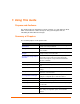
1: Using This Guide Purpose and Audience This guide provides the information needed to configure, use, and update the XPort AR™. It is intended for software developers and system integrators who are embedding the XPort AR in their designs. Summary of Chapters The remaining chapters in this guide include: Chapter Description 2: Description and Specifications Main features of the product and the protocols it supports. Includes technical specifications.
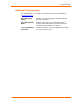
1: Using This Guide Additional Documentation The following guides are available on the product CD or the Lantronix Web site (www.lantronix.com): XPort AR Getting Started Provides the steps for getting the XPort AR evaluation board up and running. XPort AR Integration Guide Provides information about the XPort AR hardware, testing the XPort AR using the evaluation board, and integrating the XPort AR into your product.
2: Description and Specifications This chapter summarizes the XPort AR device server’s features and basic information needed before getting started.
2: Description and Specifications Time/attendance clocks and terminals Protocol Support The XPort AR device server contains a full-featured TCP/IP stack. Supported protocols include: ARP, IP, UDP, TCP, ICMP, BOOTP, DHCP, Auto IP, Telnet, FTP, TFTP, HTTP, SSH, SSL, SNMP, and SMTP for network communications and management. TCP, UDP, TCP/AES, UDP/AES, Telnet, and SSH for tunneling to the serial port. TFTP, FTP, and HTTP for firmware upgrades and uploading files.
2: Description and Specifications Web Manager: Through a web browser, configure the XPort AR’s settings using the Lantronix Web Manager. (See 4:Configuration Using Web Manager.) Command Mode: There are two methods to accessing Command Mode: making a Telnet connection or connecting a terminal (or a PC running a terminal emulation program) to the unit’s serial port. (See 5:Configuration Using Telnet or Serial Port.
2: Description and Specifications Product Information Label The product information label on the underside of the unit contains the following information about the specific unit: Bar code Serial number Product ID (name) Part number Hardware address (MAC address) Figure 2-2.
3: Using DeviceInstaller This chapter covers the steps for viewing the XPort AR device server’s properties and device details. Accessing XPort AR using DeviceInstaller Note: Make note of the MAC address. It is needed to locate the XPort AR using DeviceInstaller. Follow the instructions on the product CD to install and run DeviceInstaller. 1. Click StartÆPrograms Æ LantronixÆDeviceInstallerÆDeviceInstaller. 2. Click on the XPort AR folder. The list of Lantronix XPort AR devices available displays. 3.
3: Using DeviceInstaller Extended Firmware Version Provides additional information on the firmware version. Online Status Non-configurable field. Displays the XPort AR’s status as online, offline, unreachable (the XPort AR is on a different subnet), or busy (the XPort AR is currently performing a task). Telnet Enabled Displays whether Telnet is enabled on this XPort AR. Telnet Port Non-configurable field. Displays the XPort AR’s port for telnet sessions.
4: Configuration Using Web Manager This chapter describes how to configure the XPort AR using Web Manager, Lantronix’s browser-based configuration tool. The unit’s configuration is stored in nonvolatile memory and is retained without power. All changes take effect immediately, unless otherwise noted. Accessing Web Manager through a Web Browser Log into the XPort AR using a standard Web browser. Note: Alternatively, access the Web Manager by selecting the Web Configuration tab from DeviceInstaller.
4: Configuration Using Web Manager Network Settings Click the Network link on the left navigation bar to display the Network menu. The sub-menus displayed allow for the configuration of the general network settings, protocol stack, DNS, SNMP, FTP, TFTP, IP address filter, and the query port. Network Configuration To configure the network’s general configuration: 1. Click Network Æ Configuration from the navigation menu. The Network Configuration window displays. Figure 4-2.
4: Configuration Using Web Manager 2. Enter or modify the following fields: BOOTP Client Select On or Off. Overrides the configured IP address, network mask, gateway, hostname, and domain. Note: When DHCP is set to On, the system automatically uses DHCP, regardless if BOOTP Client is set to On. DHCP Client Select On, Off, or Renew. Overrides the configured IP address, network mask, gateway, hostname, and domain. IP Address Enter the XPort AR’s static IP address.
4: Configuration Using Web Manager Figure 4-3. Protocol Stack 2. Enter or modify the following fields: TCP Send RSTs TCP contains six control bits, with one or more defined in each packet. RST is one of the control bits. The RST bit is responsible for telling the receiving TCP stack to immediately end a connection. Sending this flag may pose a security risk. Select Off to disable the sending of the RST flag.
4: Configuration Using Web Manager Note: Both the IP and MAC addresses are required for the ARP cache. Current State Clear Select Clear to remove all entries in the ARP table. Remove Removes a specific entry from the ARP table. 3. Click Submit after each modified field. Changes are applied immediately to the XPort AR. PPP Point-to-Point Protocol (PPP) establishes a direct connection between two nodes.
4: Configuration Using Web Manager Peer IP Address Enter the IP address assigned to the peer (when requested during negotiation). Network Mask Enter the network mask. Auth. Mode Choose the authentication mode. Select None when no authentication is required. Select PAP for Password Authentication Protocol. Select CHAP for the Challenge Handshake Authentication Protocol. 3. Click Submit. Changes are applied immediately to the XPort AR DNS Configuration To configure the XPort AR’s DNS configuration: 1.
4: Configuration Using Web Manager Figure 4-6. SNMP Configuration 2. Enter or modify the following fields: SNMP Agent Select On to enable SNMP. Read Community Enter the SNMP read-only community string. Write Community Enter the SNMP read/write community string. System Contact Enter the name of the system contact. System Name Enter the system name. System Description Enter the system description. System Location Enter the system location.
4: Configuration Using Web Manager Figure 4-7. FTP Configuration 2. Enter or modify the following fields: FTP FTP Server Select On to enable the FTP server. Username Enter the username to use when logging in via FTP. Password Enter the password to use when logging in via FTP. 3. In the Current FTP Configuration and Statistics tables, reset currently stored fields as necessary by clicking the Reset link. 4. Click Submit. Changes are applied immediately to the XPort AR.
4: Configuration Using Web Manager 2. Enter or modify the following fields: TFTP TFTP Server Select On to enable the FTP server. Allow TFTP File Creation Enable the automatic creation of files stored by the TFTP server. 3. In the Current TFTP Configuration and Statistics table, reset currently stored fields as necessary by clicking the Reset link. 4. Click Submit. Changes are applied immediately to the XPort AR.
4: Configuration Using Web Manager supported. For more information on DeviceInstaller, see Using DeviceInstaller on page 15. To configure the query port server: 1. Click Network Æ Query Port from the navigation menu. The Query Port window opens to display the current configuration. Figure 4-10. Query Port Configuration 2. Select On to enable the query port server. 3. Click Submit. Changes are applied immediately to the XPort AR.
4: Configuration Using Web Manager Figure 4-11. Line 1 Configuration 2. Enter or modify the following fields: Status Displays the whether the current line is enabled. To change the status, select Enabled or Disabled from the pull-down menu. Baud Rate Select the XPort AR’s baud rate from the pull-down menu. The default is 9600. Parity Select the XPort AR’s parity from the pull-down menu. The default is None. Data Bits Select the number of data bits from the pull-down menu. The default is 8.
4: Configuration Using Web Manager Figure 4-12. Line 1 Command Mode 2. Enter or modify the following fields: Always Select Yes to enable the XPort AR’s command mode. Use Serial String Select Yes to start command mode based on a serial string. Use CP Group Select Yes to start command mode based on the value of a CP group. Echo Serial String Select Yes to enable echoing of the serial string at boot-up. Wait Time Enter the wait time for the serial string during boot-up.
4: Configuration Using Web Manager accept mode, disconnect mode, packing mode, start and stop characters, and modem emulation. Note: The following section describes the steps to configure Tunnel 1; these steps also apply to Tunnel 2 menu options. Figure 4-13. Tunnel 1 Serial Settings To configure serial settings: 1. Click Tunnel 1 Æ Serial Settings from the navigation menu. The Tunnel 1 Serial Settings window displays. Figure 4-14.
4: Configuration Using Web Manager 2. Enter or modify the following fields: Buffer Size Enter the buffer size used for the tunneling of data received. Read Timeout Enter the time, in milliseconds, for tunneling wait for serial data Wait for Read Timeout Select Enabled to cause the tunneling to wait for a read timeout before returning serial data. 3. In the Current Configuration table, reset currently stored fields as necessary. 4. Click Submit. Changes are applied immediately to the XPort AR.
4: Configuration Using Web Manager 2. Enter or modify the following fields: Mode Select Disabled to turn off connect mode. Any Character enables connect mode upon receiving a character. Start Character enables connect mode upon receiving the start character. Select DSR Active to enable Connect Mode if Data Set Ready (DSR) pin is active on the serial line. Select Modem Emulation to use modem emulation on this tunnel. Remote Address Enter the remote address to which the XPort AR will connect.
4: Configuration Using Web Manager Figure 4-16. Tunnel 1 Accept Mode 2. Enter or modify the following fields: Mode Select Disabled to disable Accept Mode completely. Select Enable to enable Accept Mode at all times. Select Any Character to enable Accept Mode upon receiving any character or select Start Character to enable Accept Mode upon receiving the start character. Select DSR Active to enable Accept Mode if the Data Set Ready (DSR) pin is active on the serial line.
4: Configuration Using Web Manager On Connection Specifies the value to set the CP or CP Group when a connection is established. On Disconnection Specifies the value used when the connection is closed. 3. Click Submit. Changes are applied immediately to the XPort AR. Disconnect Mode Disconnect mode is disabled by default. When enabled, disconnect mode runs in the background of an active connection to determine when a disconnection is required. To configure the tunnel’s disconnect mode: 1.
4: Configuration Using Web Manager To configure the tunnel’s packing mode: 1. Select Tunnel 1 Æ Packing Mode from the navigation menu. The Tunnel 1 Packing Mode window displays. Figure 4-18. Tunnel 1 Packing Mode 2. Enter or modify the following fields: Mode Select Disabled to disable Packing Mode completely. Select Send Character to send the queued data when the Send Character is received. Select Timeout to send data after the specified time has elapsed.
4: Configuration Using Web Manager Figure 4-19. Tunnel 1 Start/Stop Chars 2. Enter or modify the following fields: Start Character Enter the start character in either ASCII or hexadecimal notation. Stop Character Enter the start character in either ASCII or hexadecimal notation. Echo Start Character Select On to forward (tunnel) the start character. Echo Stop Character Select On to forward (tunnel) the stop character. 3. Click Submit. Changes are applied immediately to the XPort AR.
4: Configuration Using Web Manager 2. Enter or modify the following fields: Echo Pluses Select On to echo “+++” when entering modem command mode Echo Commands Select On to echo the modem commands to the console. Verbose Response Codes Select On to send modem response codes out on the serial line. Response Codes Select the type of response code from either Text or Numeric. Connect String Enter the connect string. This modem initialization string prepares the modem for communications.
4: Configuration Using Web Manager 2. Enter or modify the following fields: Encrypt Key Enter the value for each byte. From the pull-down menu, select the format for the byte as either character, hexadecimal, or decimal notation. Note: Any empty trailing bites that are not specified are set to 0. Decrypt Key Enter the value for each byte of the decrypt key. From the pull-down menu, select the format for the byte as either character, hexadecimal, or decimal notation.
4: Configuration Using Web Manager 2. Enter or modify the following fields: Encrypt Key Enter the value for each byte. From the pull-down menu, select the format for the byte as either character, hexadecimal, or decimal notation. All trailing bytes not specified are set to 0. Decrypt Key Enter the value for each byte of the decrypt key. From the pull-down menu, select the format for the byte as either character, hexadecimal, or decimal notation. All trailing bytes not specified are set to 0. 3.
4: Configuration Using Web Manager Current Configuration CP Indicates the Configurable Pin number. Pin # Indicates the hardware pin number associated with the CP. Configured As Displays the CPs configuration. A CP configured as Input is set to read input. A CP configured as Output drives data out of the XPort AR. Peripheral is a setting assigned by the XPort AR. State A value of 1 means asserted. 0 means de-asserted. I indicates the CP is inverted.
4: Configuration Using Web Manager CPM: Groups The CP Groups page allows for the management of CP groups. Create a CP group and add CPs to it. A group, based on its state, triggers outside events (such as sending email messages). Only an enabled group can be used as a trigger. To configure the XPort AR’s CP groups: 1. Click CPM Æ Groups from the navigation menu. The CPM: Groups window displays. Figure 4-24. CPM: Groups 2.
4: Configuration Using Web Manager Value Displays the CP group’s current value. Bit Visual display of the 32 bit placeholders for a CP. I/O A “+” symbol indicates the CP’s bit position is asserted (the voltage is high). A “-“ indicates the CP voltage is low. Logic An “I” indicates the CP is inverted. State Displays the assertion value of the corresponding bit. CP# Displays the Configurable Pin number and its bit position in the CP group. 2.
4: Configuration Using Web Manager SSH Settings Secure Shell (SSH) is a protocol used to access a remote computer over an encrypted channel. It is a protocol for managing the security of data transmission over the Internet. It provides encryption, authentication, and message integrity services. Select the SSH link on the left menu bar to display the SSH menu over an encrypted channel.
4: Configuration Using Web Manager 4. To create new keys, select the following option buttons: Create New Keys Key Type Select RSA or DSA. Bit Size Select the size of the key. Large bit keys require more time to generate. Note: Certain SSH clients require RSA host keys to be at least 1024 bits. 5. Click Submit. Changes are applied immediately to the XPort AR. SSH Server’s Authorized Users To configure the SSH server’s authorized users: 1. Click SSH Æ Server Authorized Users from the navigation menu.
4: Configuration Using Web Manager SSH Client Known Hosts To configure the SSH client’s known hosts: 1. Click SSH Æ Client Known Hosts from the navigation menu. The SSH Client: Known Hosts window displays. Figure 4-27. SSH Client: Known Hosts 2. Enter or modify the following fields: Server Enter the hostname or IP address of the remote server location. Public RSA Key Click Browse to locate the public RSA key to use when authenticating the connection to the server.
4: Configuration Using Web Manager Figure 4-28. SSH Client: Users 2. Enter or modify the following fields: Username Enter the XPort AR’s username for use when connecting to the server. Password Enter the password associated with the username. Remote Command Enter the remote command to provide to the server. This command triggers the desired or appropriate application to execute. A shell starts by default.
4: Configuration Using Web Manager SSL Settings Secure Socket Layer (SSL) is a protocol for managing the security of data transmission over the Internet. It provides encryption, authentication, and message integrity services. SSL is widely used for secure communication to a web server. Select the SSL link on the left menu bar to display the SSL menu. The Web Manager also permits the creation of self-signed certificates.
4: Configuration Using Web Manager 3. Click Submit. Changes are applied immediately to the XPort AR. 4. To create a new self-signed certificate, enter the following information: Create New Self-Signed Certificate Country Enter the 2-letter country code. State/Province Enter the state or province within the country. Locality Enter the city within the State/Province. Organization The name of the organization owning the certificate.
4: Configuration Using Web Manager Figure 4-31. Command Line Interface Configuration 2. Enter or modify the following fields: Telnet Access Select On to enable Telnet access. Telnet is enabled by default. Telnet Port Enter the Telnet port to use for Telnet access. The default is 23. SSH Access Select On to enable SSH access. SSH is enabled by default. SSH Port Enter the SSH port to use for SSH access. The default is 22. Password Enter the password for Telnet access.
4: Configuration Using Web Manager Figure 4-32. HTTP Statistics HTTP Configuration To configure HTTP: 1. Click HTTP Æ HTTP Configuration from the navigation menu. The HTTP Configuration window opens. Figure 4-33.
4: Configuration Using Web Manager 2. Enter or modify the following fields: HTTP Server Select On to enable the HTTP server. HTTP Port Enter the port for the HTTP server to use. The default is 80. HTTPS Port Enter the port for the HTTPS server to use. The default is 443. The HTTP server only listens on the HTTPS Port when an SSL certificate is configured. Max Timeout Enter the maximum time for the HTTP server to wait when receiving a request. This prevents Denial-of-Service (DoS) attacks.
4: Configuration Using Web Manager Figure 4-34. HTTP Authentication 2. Enter or modify the following fields: URI Enter the Uniform Resource Identifier (URI). Realm Enter the domain, or realm, used for HTTP. Required with the URI field. Auth Type Select the authentication type. None means no authentication is necessary. Basic encodes passwords using Base64. Digest encodes passwords using MD5. SSL means the page can only be accessed over SSL (no password is required).
4: Configuration Using Web Manager To configure HTTP RSS settings: 1. Click HTTP Æ RSS from the navigation menu. The HTTP RSS window opens and displays the current RSS configuration. Figure 4-35. HTTP RSS 2. Enter or modify the following fields: RSS Feed Select On to enable RSS feeds to an RSS publisher. Persistent Select On to enable the RSS feed to be written to a file (cfg_log.txt) and available across reboots. Max Entries Sets the maximum number of log entries.
4: Configuration Using Web Manager Figure 4-36. Import System Configuration 2. Use one of the following methods to import the XCR file: a) To import an XCR file from the filesystem, select Import XCR file from the filesystem and enter the filename on the XPort AR containing the file to import. b) To import an external file, select Import external XCR file and click Browse. Locate the file in the Choose File window. 3. (Optional) Enter the filter to apply in the Filter field.
4: Configuration Using Web Manager Export System Configuration To export and store an XPort AR’s configuration: 1. Click XML Æ Export from the navigation menu. The XML: Export System Configuration window opens. Figure 4-37. Export System Configuration 2. Use one of the following methods to export the XCR file: a) To view the XCR data (without storing it), select Export ECR data to browser. b) To export to a file on the XPort AR filesystem, select Export XCR data to the filesystem.
4: Configuration Using Web Manager 4. Click Export. The groups display if exporting the data to the browser. If exporting to the filesystem, the files are stored on the filesystem. (To view these files or store them elsewhere, see Filesystem Configuration on page 56.) Email Configuration The XPort AR allows for the configuration of four email alerts relating to the Configuration Pins (CPs). Select the Email link on the left menu bar to display the Email menu and statistics.
4: Configuration Using Web Manager 2. Enter or modify the following fields: To Enter the email address to which the email alerts will be sent. CC Enter the email address to which the email alerts will be CC’ed. From Enter the email address to list in the From field of the email alert. Reply-To Enter the email address to list in the Reply-To field of the email alert. Subject Enter the subject for the email alert. File Enter the path of the file to send with the email alert.
4: Configuration Using Web Manager To compact or format the XPort AR’s filesystem: 1. Click Filesystem from the navigation menu. The Filesystem window opens and displays the current filesystem statistics and usage. 2. To compact the files, click Compact. Note: Data can be lost if power is cycled when compacting the filesystem. 3. To reformat the filesystem, click Format. Note: All files and configuration settings on the filesystem are destroyed upon formatting, including Web Manager files.
4: Configuration Using Web Manager 3. Click the X next to a filename to delete the file or directory. A directory can only be deleted if it is empty. 4. Enter or modify the following fields: Note: Changes apply to the current directory view. To make changes within other folders, click on the folder or directory and then enter the parameters in the fields listed below. Create File Enter a filename and click Create. The XPort AR creates the empty file (0 bytes) and stores it in the current directory.
4: Configuration Using Web Manager Diagnostics Configuration The XPort AR has several tools for diagnostics and statistics. Select the Diagnostics link on the left menu bar to display the Diagnostics menu. The submenus allow for the configuration or viewing of MIB2 statistics, IP socket information, ping, traceroute, DNS lookup, memory, buffer pools, processes, and hardware. MIB2 Statistics To view XPort AR’s MIB2 statistics: 1. Click Diagnostics Æ MIB2 Statistics from the navigation menu.
4: Configuration Using Web Manager Figure 4-43. IP Sockets Ping To ping a remote device or computer: 2. Click Diagnostics Æ Ping from the navigation menu. The Diagnostics: Ping window opens. Figure 4-44. Diagnostics: Ping 3. Enter or modify the following fields: Host Enter the IP address for the XPort AR to ping. Count Enter the number of ping packets XPort AR should attempt to send to the Host. The default is 3.
4: Configuration Using Web Manager Traceroute To use traceroute from the XPort AR: 1. Click Diagnostics Æ Traceroute from the navigation menu. The Diagnostics: Traceroute window opens. Figure 4-45. Diagnostics: Traceroute 2. Enter or modify the following fields: Traceroute Enter the IP address or DNS hostname. This address is used to show the path between it and the XPort AR when issuing the traceroute command. 3. Click Submit. The results of the traceroute display in the window.
4: Configuration Using Web Manager 2. Enter or modify the following field: Lookup Enter an IP address for reverse lookup to locate the hostname for that IP address. Enter a hostname for forward lookup to locate the corresponding IP address. Enter a domain name (prefixed with “@”) to look up the Mail Exchange (MX) record IP address. 3. Click Submit. The results of the lookup display in the window. Memory To display memory statistics for the XPort AR: 1.
4: Configuration Using Web Manager Figure 4-48. Diagnostics: Buffer Pools Processes The XPort AR Processes window displays all the processes currently running on the system. It displays the Process ID (PID), the percentage of total CPU cycles a process used within the last 2 seconds, the total stack space available, the maximum amount of stack space used by the process since it started, and the process name. To display the processes running on the XPort AR and their associated statistics: 1.
4: Configuration Using Web Manager Note: The Adobe SVG plug-in is required to view the CPU Load Graph. Hardware The Hardware window displays basic hardware information and allows for the modification of the CPU speed. To display the XPort AR’s hardware diagnostics: 1. Click Diagnostics Æ Hardware from the navigation menu. The Diagnostics: Hardware window opens and displays current the current hardware configuration. Figure 4-50. Diagnostics: Hardware 2.
4: Configuration Using Web Manager Figure 4-51. System To configure the XPort AR’s system settings: 1. Click System from the navigation menu. The System window opens. 2. Configure the XPort AR’s system using the following fields: Reboot Device Click Reboot to reboot the XPort AR. The system refreshes and redirects the browser to the XPort AR’s home page. Restore Factory Defaults Click Factory Defaults to restore the XPort AR to the original factory settings. All configurations will be lost.
5: Configuration Using Telnet or Serial Port Configure the XPort AR so that it can communicate on a network with your serial device. For example, set the way the unit responds to serial and network traffic, how it handles serial packets, and when to start or close a connection. As an alternative to using Web Manager, configure the XPort AR using a series of prompts referred to as Command Mode, accessed through a Telnet or a serial port connection. The configuration may be changed at any time.
5: Configuration Using Telnet or Serial Port Navigating the Command Line Interface Commands at the root level (top level) of the CLI do not affect current configuration settings. Commands within the Enable menu (and its sub-menus) modify the XPort AR’s configuration. Items within < > (e.g. ) are required parameters. To view acceptable commands enter “?”. To move to a sub-level and traverse the tree of commands, enter each sub-command only in its parent command prompt.
5: Configuration Using Telnet or Serial Port XPort AR CLI Level Hierarchy XPort AR User Guide 68
5: Configuration Using Telnet or Serial Port Root Configuration Menu Top level root commands do not alter the configuration of the XPort AR. Clrscrn Clears the screen. Enable Displays the Enable level prompt. Within this menu, changes can be written to the XPort AR. For the list of Enable prompts, see Enable Menu on page 70. Exit Exit from the system. Ping Pings the host destination 5 times with a 5 second timeout.
5: Configuration Using Telnet or Serial Port Enable Menu The following sections describe the configurable parameters within the Enable configuration menu. Auto show interfaces Displays interface statistics. Auto show processes Continuously displays thread runtime information. Chem Change from the Enable menu to the Configure Email 1 (Chem) sub-menu. For the list of Chem prompts, see Chem Menu on page 74. Chem 1 Change from the Enable menu to the Configure Email 1 (Chem) sub-menu.
5: Configuration Using Telnet or Serial Port Clear query port counters Sets to zero the Query Port counters. Clear ssh Ends an active SSH session on the XPort AR. Clear telnet Ends an active Telnet session on the XPort AR. Configure Displays the Configuration level menu. For the list of commands within this menu, see Configure Menu on page 78. CPM Displays the Configuration Pin Manager (CPM) level menu. For the list of commands within this menu, see CPM Menu on page 91.
5: Configuration Using Telnet or Serial Port Line3 Displays the Line 3 menu for serial port 3 configuration. For more information on serial port configuration, see Line Menu on page 99. No clear interfaces counters Reverts the interface counters to the last aggregate value. No clear query port counters Reverts the query port counters to the last aggregate value. Nslookup Look up host information for the given host name. Nslookup Display host information for a specified host name.
5: Configuration Using Telnet or Serial Port Show history Displays previously entered commands. Show hosts Displays the domain settings. Show interfaces Displays network interface statistics. Show ip sockets Displays TCP and UDP state information and their associated ports. Show processes Displays thread runtime information. This command shows the list of running processes. The stack is the number of bytes used and the total stack size.
5: Configuration Using Telnet or Serial Port Write Store and apply current configuration into permanent memory. Xcr dump Display the XML configuration to the console. For more information on XML, see XML on page 134. Xcr dump Display a specified XML configuration to the console. Separate groups with a comma. Specify group instances (if they exist) with a colon. For example: > xcr dump line:1, line:2 Enclose groups with a white space in the name with double quotation marks.
5: Configuration Using Telnet or Serial Port Cc Enter the email address to which the alert email is CC’ed. Separate multiple addresses with a semi-colon. Chem 2 Displays the Chem 2 menu for configuration. Chem 3 Displays the Chem 3 menu for configuration. Chem 4 Displays the Chem 4 menu for configuration. Clear log Clears all entries from the mail log. Clear mail counters Set to zero the mail counters. CP send Specify a CP group and its value to trigger an email.
5: Configuration Using Telnet or Serial Port No cc Clears the CC field in the email. No clear mail counters Reverts the mail counters to the last aggregate value. No cp send Disable the CP trigger used to send the email. No file Removes the file used for the body of the email. No from Clears the “From” heading line in the email. No overriding domain Removes the overriding domain name option. No replyto Clears the Reply-To field in the email. No subject Clears the email’s Subject field.
5: Configuration Using Telnet or Serial Port Priority urgent Sets the email priority level to urgent. Displays as urgent priority if recipient’s email supports email priority settings. Corresponds to X-Priority level 1. Priority very low Sets the email priority level to very low. Displays as very low priority if recipient’s email supports email priority settings. Corresponds to X-Priority level 5. Replyto Enter the Reply-To email address.
5: Configuration Using Telnet or Serial Port Configure Menu The following sections describe the configurable parameters within the Configure menu. Arp Address Resolution Protocol (ARP) maps an IP address to a device’s MAC address. The arp command adds an entry to the ARP table. Auto show icmp Continuously displays ICMP state and statistics. Auto show ip Continuously displays IP statistics.
5: Configuration Using Telnet or Serial Port Clear ip counters Set the IP counters to zero. Clear ip ssh counters Set the SSH counters to zero. Clear ip telnet counters Set the Telnet counters to zero. Clear rss Clears the RSS feed data. Clear ssh End an active SSH session on the XPort AR. Clear tcp counters Set to zero the TCP counters. Clear telnet End an active Telnet session on the XPort AR. Clear tftp counters Sets the TFTP counters to zero. Clear udp counters Set the UDP counters to zero.
5: Configuration Using Telnet or Serial Port Hostname Set the system hostname. If 1 Display the Interface 1 menu. For more information on serial port configuration, see Interface 1 Level Menu on page 88. Ip domain name Set the default domain name on the XPort AR. Ip ftp enable Enable the FTP server. Ip ftp password Set the administrative password for the FTP server.
5: Configuration Using Telnet or Serial Port IP http auth type ssl-basic Set the authentication type for an HTTP server authentication directive to SSL-Basic. IP http auth type ssl-digest Set the authentication type for an HTTP server authentication directive to SSLDigest. IP http auth user Create or modify a user for an HTTP server authentication directive. IP http log Enable HTTP server logging.
5: Configuration Using Telnet or Serial Port IP icmp enable Allow the transmission and retrieval of Internet Control Message Protocol (ICMP) packets. Ip name-server Set the primary DNS server. Ip name-server Set the primary and secondary DNS servers. Ip ssh enable Enable the SSH server. Ip ssh port Set the local port for SSH that the server uses. Ip tcp resets enable Sends TCP RSTs upon connection to unused ports.
5: Configuration Using Telnet or Serial Port No clear ftp counters Revert the FTP counters to the last aggregate value. No clear ip ssh counters Revert the IP SSH counters to the last aggregate value. No clear ip telnet counters Reverts the IP Telnet counters to the last aggregate value. No clear tcp counters Revert the TCP counters to the last aggregate value. No clear tftp counters Revert the TFTP counters to the last aggregate value.
5: Configuration Using Telnet or Serial Port No ip http auth log Disables HTTP server logging. No ip http auth log format Removes the log format string for the HTTP server. No ip http server Disables the HTTP server. No ip icmp enable Prevents the sending or retrieval of ICMP packets. No ip name-server Remove the name server. No ip ssh enable Disables and stops the SSH server. No ip tcp resets enable Prohibits TCP RSTs from sending on connect to unused ports.
5: Configuration Using Telnet or Serial Port No rss enable Disables the RSS feed. No rss persistent Disables RSS feed data persistence. No snmp-server community ro Remove the SNMP read-only server community string. No snmp-server community rw Remove the SNMP read/write server community string No snmp-server contact Remove the SNMP server contact. No snmp-server description Clear the SNMP server description. No snmp-server enable Disable the SNMP server.
5: Configuration Using Telnet or Serial Port Password Set the new password. Prompts for a password then requests password verification. Password Enter the password on one line. Ppp 1 Display the PPP menu for serial port 1. For more information on PPP configuration, see PPP Menu on page 91. Ppp 2 Display the PPP menu for serial port 2. For more information on PPP configuration, see PPP Menu on page 91. Query-port enable Enable the query port.
5: Configuration Using Telnet or Serial Port Show ip Show IP statistics. Show rss Show the RSS feed settings. Show snmp-server Display SNMP server settings. Show ssh Display IP SSH configuration. Show telnet Display Telnet configuration. Show tftp Display TFTP settings and statistics. Show udp Display UDP settings and statistics Snmp-server community ro Set the read-only SNMP server community. Snmp-server community rw Set the read-write community within the SNMP server.
5: Configuration Using Telnet or Serial Port Snmp-server enable traps Enable traps on the SNMP server. Snmp-server host Set the primary SNMP trap host. Snmp-server host Set the primary and secondary SNMP trap hosts. Snmp-server location Set the SNMP system location. Snmp-server name Set the SNMP system name. Write Store and apply current configuration into permanent memory.
5: Configuration Using Telnet or Serial Port Dhcp renew Force DHCP to renew. Exit Exit the Interface menu and returns to the Enable menu (see Enable Menu on page 70). IP address Set the IP address and netmask. Enter the netmask in CIDR notation. IP address Set the IP address. IP address Set the IP address and netmask. Enter the netmask in dotted notation. IP address filter Add a filter to the IP filter table.
5: Configuration Using Telnet or Serial Port No ip default-gateway Remove the default gateway. Show Show interface settings. Show history Display previously-entered commands. Show ip address filter Display the IP filter table. Speed 10 Set the Ethernet link to 10 Mbps (duplex is unchanged). Speed 10 full Set the Ethernet link to 10M bps (full-duplex). Speed 10 half Set the Ethernet link to 10 Mbps (half-duplex). Speed 100 Set the Ethernet link to 100 Mbps (duplex is unchanged).
5: Configuration Using Telnet or Serial Port PPP Menu The following section describes the configurable parameters within the Point-to-Point Protocol (PPP) configuration menu. For more information on PPP, see Point-to-Point Protocol (PPP) on page 119. Note: The following section describes the parameters within the PPP 1 and PPP 2 menus. Exit Exit the CPM menu and return to the Enable menu (see Enable Menu on page 70). Ip address Sets the local IP address and netmask.
5: Configuration Using Telnet or Serial Port Ppp enable Enables PPP. Show Displays the current PPP configuration. Username password Sets the PPP authentication username and password. Write Store and apply current configuration into permanent memory. CPM Menu The following section describes the configurable parameters within the CPM configuration menu. For more information on the CPM, see Configuration Pin Manager on page 131.
5: Configuration Using Telnet or Serial Port Disable Disable a group and make all CPs available. Enable Enable a disabled CP group. Exit Exit the CPM menu and return to the Enable menu (see Enable Menu on page 70). Get Display the value of a specified CP group. Set Assign a value to a specified group. Set as input Configure a CP as an assert high input. Set as input assert low Configure a CP as an assert low input.
5: Configuration Using Telnet or Serial Port Show history Show previously-entered commands. Write Write runtime configuration to permanent storage. Device Menu The following section describes the configurable parameters within the Device configuration menu. Clrscrn Clears the screen. CPU speed Set the CPU speed. Dvt Displays the DVT menu For more information on DVT configuration, see DVT on page 95. Exit Exit the Device menu and return to the Enable menu (see Enable Menu on page 70).
5: Configuration Using Telnet or Serial Port Short name Set the XPort AR’s short name, displayed in Command Mode and the Web Manager. The string is a maximum 8 characters. Show Displays system information. Show buffer pool Displays information on buffer pools. Show hardware information Display the hardware information for the XPort AR. Shows the CPU type, CPU speed, Hardware ID, flash size, RAM size, and hard drive size. Show history Display previously-entered commands.
5: Configuration Using Telnet or Serial Port Dvt eeprom Configure non-destructive DVT of Electrically-Erasable Programmable Read-Only Memory (EEPROM). EEPROM is a non-volatile storage chip used in computers and other devices. Dvt ethernet Configure non-destructive DVT for the Ethernet interface. Dvt hardware id Configure the DVT hardware ID. Dvt line Configure nondestructive DVT of a specific line (i.e. the serial port).
5: Configuration Using Telnet or Serial Port Cp Create a copy of an existing file. The first string parameter is the original file, the second string parameter is the name for the copied file. Dump Display the contents of a specified file. Exit Exit the Filesystem menu and return to the Enable menu (see Enable Menu on page 70). Format Display all filesystem files and directories. Ls Display all filesystem files in the current directory.
5: Configuration Using Telnet or Serial Port Show Show filesystem statistics. Show history Show previously entered commands. Show tree Show all filesystem files and directories. Tftp get ascii Obtain an ASCII file using TFTP. Tftp get ascii Obtain an ASCII file using TFTP. Tftp get binary Obtain a binary file using TFTP.
5: Configuration Using Telnet or Serial Port Tftp put binary Send a binary file using TFTP. Tftp put binary Send a binary file using TFTP. Touch Create a file on the filesystem. Enter the filename to be created. Line Menu The following sections describe the configurable parameters within the Line 1, Line 2, and Line 3 configuration menus. These configure serial ports 1, 2, and 3.
5: Configuration Using Telnet or Serial Port Command mode serial string Set command mode to use serial settings. Command mode serial string Set command mode serial string using ASCII characters. Command mode serial string binary Set command mode serial string using binary values. Command mode signon message Set the boot-up sign-on message using ASCII characters. Command mode signon message binary Set boot-up sign-on message using binary values.
5: Configuration Using Telnet or Serial Port No clear line counters Reverts the serial counters to the last aggregate value. Line 2 Displays the Line 2 menu. Line 3 Displays the Line 3 menu No command mode Disables command mode. No command mode echo Disables the echoing of serial data upon bootup. No command mode cp Disables the Command Mode use of CP settings. No command mode serial string Disables the Command Mode use of serial settings.
5: Configuration Using Telnet or Serial Port Parity odd Set the XPort AR’s parity to odd. Show Display the XPort AR’s settings. Show command mode Show Command Mode settings. Show line Show line settings. Show statistics Show line statistics. Shutdown Disables the interface. Speed Set the XPort AR’s speed to values between 300 and 230400. Speed custom Set the XPort AR’s speed to values between 300 and 230400. Stopbits 1 Set the XPort AR’s stop bit to 1.
5: Configuration Using Telnet or Serial Port Xoff Sets the xoff character. Xon Sets the xon character. SSH Menu The following sections describe the configurable parameters within the SSH configuration menus. For more information on SSH, see SSH and SSL Security on page 125. Client server Set the client server RSA or DSA keys. Client user Set the client user, command, and RSA or DSA keys.
5: Configuration Using Telnet or Serial Port Client user generate rsa 512 Generate RSA public and private keys. Client user generate rsa 768 Generate RSA public and private keys. Clrscrn Clears the screen. Exit Exit the SSH menu and return to the Enable menu (see Enable Menu on page 70). Host Sets the RSA or DSA public (or private) keys. Host Sets the RSA or DSA public (or private) key. Host Sets RSA (or DSA) public and private keys.
5: Configuration Using Telnet or Serial Port Host generate rsa 768 Generate RSA public and private keys. Host user Sets the host username and password. Host user Sets the host username, password and a public key. Host user Sets the host username, password, public keys, and private keys. No client server Remove the client server. No client server dsa Remove the client server DSA key.
5: Configuration Using Telnet or Serial Port No host user Remove a host user. Show Show SSH settings. Show client server Show client server RSA and DSA keys. Show client user Show information for a client user. Show host dsa Show the full DSA public key. Show host rsa Show the full RSA public key. Show host user Show information for a host user. Write Stores and apply current configuration into permanent memory.
5: Configuration Using Telnet or Serial Port Show history Displays previously-entered commands. Show ssl Displays the SSL certificate information. Ssl Adds a SSL certificate and private key. Ssl Adds a SSL certificate and private key. Ssl generate Generates a new self-signed SSL certificate. Write Stores and apply current configuration into permanent memory. Tunnel Menu The following sections describe the configurable parameters within the Tunnel configuration menu.
5: Configuration Using Telnet or Serial Port Accept any character Enable accept mode upon the reception of a character. Accept block network Block the tunneling of network data. Accept block serial Block the tunneling of serial data. Accept cp set group Enter the CP Group to set upon the creation or termination of a connection. Accept cp set group connect Sets the CP Set Group to specified value upon connection.
5: Configuration Using Telnet or Serial Port Accept protocol telnet Use Telnet (IAC) for accept mode. Accept start character Enable accept mode on reception of the start-character. Clear accept counters Set to zero the accept counters. Clear aggregate counters Set to zero the aggregate counters. Clear all counters Set to zero the all tunnel counters. Clear connect counters Set to zero the connect counters.
5: Configuration Using Telnet or Serial Port Connect any character Enable connect mode on reception of a character. Connect block network Block the tunneling of network data. Connect block serial Block the tunneling of serial data. Connect cp set group Enter the CP Group to set upon the creation or termination of a connection. Connect cp set group connect Sets the CP Set Group to specified value upon connection.
5: Configuration Using Telnet or Serial Port Connect protocol ssh Use SSH for connect mode. Connect protocol tcp Use TCP for connect mode. Connect protocol tcp aes Use AES over TCP for connect mode. Connect protocol udp Use UDP for connect mode. Connect protocol udp aes Use AES over UDP for connect mode. Connect reconnect timer Set the reconnect time value in milliseconds. Connect remote Set the remote address in which to connect. Connect remote port Set remote port.
5: Configuration Using Telnet or Serial Port Disconnect stop character Enable disconnect mode to disconnect on reception of the stop character. Disconnect timeout Enable disconnect mode to disconnect on a timeout. Disconnect timeout Set disconnect mode timeout in milliseconds. Echo start character Enable forwarding (tunneling) of the start character. Echo stop character Enable forwarding (tunneling) of stop-character.
5: Configuration Using Telnet or Serial Port Modem echo pluses Echo +++ when entering modem command mode. Modem error unknown commands Returns an error upon unknown AT commands. Modem numeric response codes Use numeric response codes. Modem text response codes Use text-based response codes. Modem verbose Use verbose status codes No accept Disable accept mode. No accept aes decryption key Remove the AES decryption key. No accept aes key encrypt Remove the AES encryption key.
5: Configuration Using Telnet or Serial Port No accept keep alive Disable TCP keepalives. No accept port Use a random port number as the local port. No clear accept counters Unzeros accept counters. No clear aggregate counters Unzeros aggregate counters. No clear all counters Unzeros all tunnel counters. No clear connect counters Unzeros connect counters. No connect Disable connect mode. No connect aes decryption key Remove the AES decryption key.
5: Configuration Using Telnet or Serial Port No connect flush serial data Do not flush serial data buffer on connection. No connect keep alive Disable TCP keepalives. No connect port Use a random port number as the local port. No connect remote address Remove remote address to connect to. No connect remote port Remove remote port to connect to. No connect ssh username No SSH user specified. No disconnect Disable disconnect mode.
5: Configuration Using Telnet or Serial Port No modem echo pluses Do not echo +++ when entering modem command mode. No modem verbose Use decimal status codes. No packing mode Disable packing mode. No packing send character Remove the send character. No packing trailing character Remove the trailing character. No serial buffer size Set buffers used in tunneling of data to the default. No serial wait for read timeout Disable waiting for read timeout before returning serial data.
5: Configuration Using Telnet or Serial Port Packing threshold Set the threshold (byte count). Packing timeout Set the timeout value in milliseconds. Packing trailing character Set the trailing character. Serial buffer size Set the size of the buffers to using in tunneling of data. Serial read timeout Set the time in milliseconds to wait for serial data.
5: Configuration Using Telnet or Serial Port Write Stores and apply current configuration into permanent memory.
6: Point-to-Point Protocol (PPP) Point-to-Point Protocol (PPP) establishes a direct connection between two nodes. It defines a method for data link connectivity between devices using physical layers (such as serial lines). Some of the PPP features include: error detection, compression, and authentication. For each of these capabilities, PPP has a separate protocol. The XPort AR supports two types of PPP authorization: Password Authentication Protocol (PAP) and Challenge Handshake Protocol (CHAP).
7: Tunneling Serial tunneling allows for devices to communicate over a network, without the realization of other devices connecting between them. Tunneling parameters are configured using the Web Manager’s Tunnel 1 and Tunnel 2 Settings (on page 28) or Command Mode’s Tunnel Menu (on page 107). The XPort AR supports 2 tunneling connections simultaneously per serial port. One of these connections is Connect Mode, the other connection is Accept Mode.
7: Tunneling When setting AES encryption, both the encrypt key and the decrypt key must be specified. The encrypt key is used for data sent out. The decrypt key is used for receiving data. Both of the keys may be set to the same value. For Connect Mode using UDP, if the remote address or port is not configured, then the XPort AR accepts packets from any device on the network. It will send packets to the last device that sent it packets. As a result, it is advised to configure the remote address and port.
7: Tunneling Telnet/IAC mode (The XPort AR currently supports IAC codes. It drops the IAC codes when telnetting and does not forward them to the serial port).
7: Tunneling Modem Emulation The XPort AR supports Modem Emulation mode for devices that send out modem signals. There are two different modes supported: Command Mode: sends back verbal response codes. Data Mode: information transferred in is also transferred out. It is possible to change the default on bootup for verbose response codes, echo commands, and quiet mode. The current settings can be overridden, however on bootup it will go back to the programmed settings.
7: Tunneling The XPort AR attempts to make a Command Mode connection as per the IP/DNS/port numbers defined in Connect Mode. It is possible to override the remote address, as well as the remote port number. Note: Configure either the IP address using the address on its own (), or the IP address and port number by entering : . The port number cannot be entered on its own.
8: SSH and SSL Security The XPort AR supports Secure Shell (SSH) and Secure Sockets Layer (SSL). These security protocols are configurable through the Web Manager (see SSH Settings on page 42 and SSL Settings on page 46) and Command Mode (see SSH Menu on page 103 and SSL Menu on page 106). Note: This chapter overviews security configuration using Web Manager. Secure Shell: SSH SSH is a network protocol for securely accessing a remote device.
8: SSH and SSL Security b) If the keys do not exist, select the Key Type and the key’s Bit Size from the Create New Keys section. Click Submit to create new private and public host keys. Note: Generating new keys with a large bit size results in very long key generation time. 3. Click SSH Æ Server Auth Users from the navigation menu. The SSH Server: Authorized Users page displays. 4. Enter the Username and Password for authorized users. 5.
8: SSH and SSL Security Alternatively, it can be automatically generated on the device; this certificate type is a self-signed certificate. Note: When uploading the certificate and the private key, ensure the private key is not compromised in transit. To upload a new certificate, see Upload Certificate on page 46. To create a new selfsigned certificate, see Create New Self-Signed Certificate on page 47.
9: Using Email The XPort AR has a Simple Mail Transfer Protocol (SMTP) client. SMTP is a TCP/IP protocol used in sending and receiving email. Its objective is to send email efficiently and reliably. There are three ways to send an email from the XPort AR: 1. Via the Web Manager (See Configuration Using Web Manager on page 17). 2. Via Command Mode by using the Send command (See Configuration Using Telnet or Serial Port on page 66). 3.
9: Using Email Priority Levels The default priority level for the XPort AR’s emails is Normal priority. The XPort AR has 5 configurable priority levels; certain recipient systems have filters based on these priority levels. Configurable priority levels are: Priority XPriority Level Urgent 1 High 2 Normal (default) 3 Low 4 Very Low 5 Some email programs may translate an Urgent priority to High, and Very Low priority to Low. The XPort AR makes an SMTP connection to a destination server.
9: Using Email Use the “Show Log” command to display the email log. When the system sends an email, the following information is logged: 1. Messages the XPort AR sends to the SMTP server. 2. Messages from the SMTP server to the XPort AR. 3. SMTP commands and replies. Note: The XPort AR does not log email message contents.
10: Configuration Pin Manager There are 11 configurable pins on the XPort AR. All CPs (except for 5) are shared by some other function on the XPort AR. Some of the CPs are assigned to serial port 1 (dtr/dsr for modem control and rts/cts for hardware flow control), others to serial port 2 (dtr/dsr for modem control, rts/cts for hardware flow control, and tx/rx groups as well). CPs are configurable individually, or may be clustered together and configured as a single group (CP group).
10: Configuration Pin Manager State A value of 1 means asserted. 0 means de-asserted. I indicates the CP is inverted. Groups Indicates the number of groups in which the CP is a member. Active In Group A CP can be a member of several groups. However, it may only be active in one group. This field displays the group in which the CP is active. CP Groups To view a CP group’s configuration: 1. If using the Web Manager: a) Click CPM Æ Groups from the navigation menu. The CPM: Groups window displays.
10: Configuration Pin Manager i. Enter a group name in the Create Group field. ii. Click Submit. Changes are applied immediately to the XPort AR. c) To delete a CP group: i. Select the CP group from the Delete Group drop-down list. ii. Click Submit. Changes are applied immediately to the XPort AR. d) To enable or disable a CP group: i. Select the CP group from the Set drop-down list. ii. Select the state (Enabled or Disabled) from the drop-down list. iii. Click Submit.
11: XML The XPort AR supports configuration using Extensible Markup Language (XML). XML’s main purpose is to assist the transmission of data across different systems. Two things are required for XML: It must be well-formed. The XML structure must adhere to general XML format rules. It must be valid. It must comply with the XML schema. Every command that is executable from the XPort AR’s Command Mode is available for configuration by XML (however, some of the commands are grouped differently).
11: XML The XPort AR’s schema (or template), is structured as following: The ELEMENT tag The XML document element is known as a ; this is the root element. Within each are the configuration groups, contained within the element. A must have one or more element. The configuration group takes “name” and “instance” attributes. Note: The items within the are the groups listed within the Web Manager groups.
11: XML Figure 11-2. XML Example With Multiple Named Values Figure 11-3. XML Example With Multiple Items john.doe@somewhere.
11: XML Configure an XPort AR with XML using the following steps: 1. Configure an XPort AR with the desired settings using the Web Manager (see Configuration Using Web Manager on page 17 ) or the Command Mode (see Configuration Using Telnet or Serial Port on page 66). 2. Export all of the settings or part of the settings of the configured XPort AR using one of the following methods: a) Using the Web Manager, select the groups to export from the XML page (see XML Configuration on page 52 ).
11: XML schema manually to ensure the XPort AR reboots after applying the XML configuration. These are labeled as Import in the Import/Export column in the following table: Table 11-1. XPort AR Import and Export Groups Group Name Item Name reboot Value Import/Export Additional Information state enable Import Force the XPort AR to reboot after processing.
11: XML Group Name Item Name Value Name Value Import/Export Additional Information 100 Import and Export Specify the speed on the Ethernet connection (10 or 100). Only valid if autonegotiation is not enabled. half Import and Export Specify the duplex of the Ethernet connection. Only valid if auto-negotiation is not enabled. full Import and Export Specify the duplex of the Ethernet connection. Only valid if auto-negotiation is not enabled.
11: XML Group Name Item Name line state Value Name Value Import/Export enable Import and Export disable Import and Export baud rate Import and Export data bits parity stop bits flow control ftp server tftp server arp 7 Import and Export 8 Import and Export none Import and Export even Import and Export odd Import and Export 1 Import and Export 2 Import and Export hardware Import and Export software Import and Export none Import and Export Additional Information Any v
11: XML Group Name Item Name Value Name Value arp delete snmp state telnet command mode Remove an entry from the ARP table. Specify the entry by its IP address.
11: XML Group Name serial command mode Item Name Value Name disable Import and Export Import and Export log format Import and Export mode disable Import and Export always Import and Export cp Import and Export serial string Import and Export cp and serial string Import and Export enable Import and Export disable Import and Export serial string Import and Export signon message Import and Export wait time Import and Export cp tunnel connect Import/Export max log entries echo
11: XML Group Name Item Name Value Name Value remote address Import and Export remote port Import and Export protocol tcp Import and Export udp Import and Export ssh Import and Export tcp aes Import and Export udp aes Import and Export reconnect time enable Import and Export disable Import and Export ssh username Import and Export block serial block network enable Import and Export disable Import and Export enable Import and Export disable Import and Export tcp keep alive
11: XML Group Name Item Name Value Name Value local port flush serial block serial block network tcp Import and Export tcp aes Import and Export ssh Import and Export telnet Import and Export enable Import and Export disable Import and Export enable Import and Export disable Import and Export enable Import and Export disable Import and Export tcp keep alive tunnel aes accept tunnel aes connect tunnel disconnect Import and Export cp Import and Export connection value Impor
11: XML Group Name tunnel packing tunnel start Item Name Value Name packing mode Import and Export disable Import and Export timeout Import and Export send character Import and Export threshold Import and Export send character Import and Export trailing character Import and Export start character Import and Export enable Import and Export disable Import and Export stop character echo pluses verbose response response type error unknown commands connect string host rsa keys XPor
11: XML Group Name Item Name authorized users ssh client rss Value Import/Export private key Import and Export username Import and Export password Import and Export public rsa key Import and Export public dsa key Import and Export Additional Information authorized users delete Import and Export Delete an SSH authorized user. host keys delete Import and Export Delete an SSH host key.
11: XML Group Name Item Name Value Name persist http authentication uri ip filter Import and Export disable Import and Export realm Import and Export type Import and Export username Import and Export password Import and Export Additional Information Attribute of "instance" specifies the uri. user delete Import Delete the HTTP Authentication URI user. The value element is used to specify the user for deletion. uri delete Import Delete the HTTP Authentication URI.
11: XML Group Name cp Item Name Value Name Import/Export peer ip Import and Export network mask Import and Export authentication mode Import and Export username Import and Export password Import and Export cp type assert low cp group Value input Import and Export output Import and Export nonpio Import and Export enable Import and Export disable Import and Export Additional Information set Import Set group named by "instance" attribute to the value.
11: XML Group Name Item Name Value Name level passwords passwords XPort AR User Guide Value Import/Export Additional Information system Import This group specifies the passwords to use when importing an XCR using the CLI capture feature. The system value specifies the root password used if the root level is password protected. Passwords are not required if the CLI is already logged in to the system level.
12: Branding the XPort AR The XPort AR’s Web Manager and Command Mode (CLI) are customizable. Web Manager Customization Customize the Web Manager’s appearance by modifying the following files: Note: To view these files, open the http Æ config folder using the Filesystem Browser. Alternatively, upload and download the files using FTP/TFTP. For more on the filesystem, see Filesystem Configuration on page 56. Filename Description index.css The Web Manager’s style sheet. footer.
13: Updating Firmware Obtaining Firmware Obtain the most up-to-date firmware and release notes for the unit from the Lantronix Web site (http://www.lantronix.com/) or by using anonymous FTP (ftp://ftp.lantronix.com/). Loading New Firmware Reload the firmware using the XPort AR’s Web Manager’s System window. To upload new firmware: 1. Click System from the navigation menu. The System window opens. 2. Click in the Upload New Firmware section, click Browse. A pop-up window displays; locate the firmware file.
A: Technical Support If you are experiencing an error that is not described in this user guide, or if you are unable to fix the error, you may: Check our online knowledge base at http://www.lantronix.com/support. Contact Technical Support in the US: Phone: 800-422-7044 (US only) or 949-453-7198 Fax: 949-450-7226 Our phone lines are open from 6:00AM - 5:30 PM Pacific Time Monday through Friday, excluding holidays.
B: Binary to Hexadecimal Conversions Many of the unit’s configuration procedures require you to assemble a series of options (represented as bits) into a complete command (represented as a byte). The resulting binary value must be converted to a hexadecimal representation. Use this chapter to learn to convert binary values to hexadecimals or to look up hexadecimal values in the tables of configuration options.
B: Binary to Hexadecimal Conversions 1. On the Windows’ Start menu, click ProgramsÆAccessoriesÆCalculator. 1. On the View menu, select Scientific. The scientific calculator displays. 2. Click Bin (Binary), and type the number you want to convert. 3. Click Hex. The hexadecimal value displays.
Compliance Information (according to ISO/IEC Guide 22 and EN 45014) Manufacturer’s Name & Address: Lantronix 15353 Barranca Parkway, Irvine, CA 92618 USA Declares that the following product: Product Name Model: Device Server PRODUCT NAME Conforms to the following standards or other normative documents: Radiated and conducted emissions Class B limits of EN 55022:1998 EN55024: 1998 + A1: 2001 Direct & Indirect ESD EN61000-4-2: 1995 RF Electromagnetic Field Immunity EN61000-4-3: 1996 Electrical Fast Transient/
Warranty Lantronix warrants each Lantronix product to be free from defects in material and workmanship for a period of TWO YEARS after the date of shipment. During this period, if a customer is unable to resolve a product problem with Lantronix Technical Support, a Return Material Authorization (RMA) will be issued. Following receipt of an RMA number, the customer shall return the product to Lantronix, freight prepaid.