
User's Manual


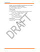


Table Of Contents
- Labeling of the End Product
- Integration Note
- Using This Guide
- Introduction
- Configuration Using DeviceInstaller
- Server Configuration
- WLAN Configuration
- Host List Configuration
- OEM Pin Configuration
- Channel 1 and Channel 2 Configuration
- Email Configuration
- Accessing WiPort using Web-Manager
- Host List Configuration
- Channel 1 and Channel 2 Configuration
- Email Configuration
- WLAN Configuration
- OEM Pin Configuration
- Updating Settings
- Configuration via Serial Mode or Telnet Port
- Configurable Pins
- Monitor Mode
- Updating Firmware
- Troubleshooting

Monitor Mode
68 WiPort™ User Guide
Command Command Name Function
PI x.x.x.x
Ping
Pings unit with IP address x.x.x.x to check device
status.
AT
ARP Table Shows the unit’s ARP table entries.
TT TCP Connection
Table
Shows all incoming and outgoing TCP connections.
NC
Network Connection Shows the unit’s current IP address.
RS
Reset Resets the unit.
QU
Quit Exits diagnostics mode.
G0, G1, ....,Ge, Gf Get configuration
from memory page
Gets a memory page of configuration information
from the device.
S0, S1,...,Se, Sf Set configuration to
memory page
Sets a memory page of configuration information
on the device.
Responses to some of the commands are given in Intel Hex format.
Note: Entering any of the commands listed above generates one of the
following command response codes:
Table 7-2. Command Response Codes
Response Meaning
0> OK; no error
1> No answer from remote device
2> Cannot reach remote device or no answer
8> Wrong parameter(s)
9> Invalid command