
User's Manual


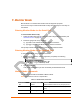


Table Of Contents
- Labeling of the End Product
- Integration Note
- Using This Guide
- Introduction
- Configuration Using DeviceInstaller
- Server Configuration
- WLAN Configuration
- Host List Configuration
- OEM Pin Configuration
- Channel 1 and Channel 2 Configuration
- Email Configuration
- Accessing WiPort using Web-Manager
- Host List Configuration
- Channel 1 and Channel 2 Configuration
- Email Configuration
- WLAN Configuration
- OEM Pin Configuration
- Updating Settings
- Configuration via Serial Mode or Telnet Port
- Configurable Pins
- Monitor Mode
- Updating Firmware
- Troubleshooting

Configurable Pins
66 WiPort™ User Guide
Example 2: PC sends command 1Bh to change the current states of GPIO 0
and 1 (assuming they are configured as outputs).
PC -> WiPort: 1Bh, 01h, 00h, 02h, 00h, 01h, 00h, 00h, 00h
WiPort -> PC: 1Bh, 03h, 00h, 00h, 00h
Command details:
1Bh = command 1Bh
01h, 00h, 00h, 00h = the mask that determines which GPIOs will be changed.
Bit 0 and 9 are 1 → GPIO0 and GPIO9 will be changed.
bit 1 is 0 → GPIO1 will remain the same.
01h, 00h, 00h, 00h = the new states
bit 0 is 1 → GPIO0 will become 1.
bit 1 is ignored since it is masked out.
bit 0 is 0 → GPIO9 will become 0..
Response details:
1Bh = response to command 1Bh
03h, 00h, 00h, 00h =
bit 0 is 1 → GPIO0 = 1
bit 1 is 1 → GPIO1 = 1
bit 9 is 0 → GPIO9 = 0