
User's Manual
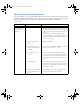

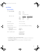
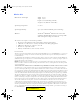
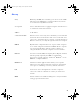
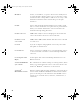
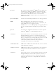
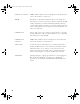
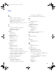
Table Of Contents
- Copyright © 2007 LifeScan, Inc. All rights reserved. No part of this publication may be reproduced, transmitted, transcribed, st...
- Disclaimer LifeScan reserves the right to change its products and services at any time to incorporate the latest technological developments. This guide is subject to change without notice.
- Trademarks OneTouch, DataLink, and SureStepPro are registered trademarks of LifeScan, Inc.
- MeterLink and Flexx are trademarks of LifeScan, Inc.
- Lantronix is a registered trademark of Lantronix.
- Windows is a registered trademark of Microsoft Corporation.
- InstallAnywhere is a registered trademark of Zero G Software, Inc.
- OneTouch® DataLink® Connection Overview 1
- OneTouch® DataLink® Sync Configuration 4
- Modem-to-Modem Configuration 9
- Serial Server/Client-to-Ethernet Configuration 10
- Serial Server/Client-to-Ethernet Configuration Using Modems 11
- Terminal Server-to-Ethernet Configuration Using Multiple Receiving Modems 13
- Connecting to the Workstation 14
- Wireless Communication 16
- Establishing Connectivity Using OneTouch® MeterLink™ Software 21
- Transferring Data 28
- Troubleshooting 33
- Specifications 39
- Glossary 41
- Index 45
- Table of Contents
- Direct Connection
- Modem Configuration
- Network Configuration
- Using This Guide
- Installing OneTouch® DataLink® Sync Software on a PC Server
- 1 Install OneTouch® DataLink® Sync on the workstation. Follow the instructions provided with the OneTouch® DataLink® Sync Installation CD.
- 2 From the PC where you wish to install OneTouch® DataLink® Sync software, use the Search/Find feature to search for the OneTouch® DataLink® workstation computer on the network.
- 3 Enter the name of the OneTouch® DataLink® workstation. The default name should be LFS_DATALINK or LFS-DATALINK.
- 4 Locate and open the DataLink Sync directory on the C drive.
- 5 Double-click install.htm.
- 6 Click Start Installer for Windows.
- 7 Click Next in the Introduction window.
- 8 Click Install to install OneTouch® DataLink® Sync software in the default directory (C:/Program Files/LifeScan/DataLink Sync). Or, if you wish to install the program in another location, click Choose and select a new directory.
- 9 Click Done in the Install Complete window.
- 10 Close the browser window.
- Connecting a OneTouch® DataLink® Connection Module to the PC Server
- Using OneTouch® DataLink® Sync Software
- Connecting a OneTouch® DataLink® Connection Module to a Sending Modem
- 1 Connect the 3-pin plug of the connection module power cord to the receptacle on the AC adapter. Then, plug the AC adapter into an AC power outlet.
- 2 Set the switches on the back of the modem as follows:
- 1
- 2
- 3
- 4
- 5
- 6
- 7
- 8
- up
- up
- down
- up
- down
- up
- down
- down
- 3 Connect the power cord from the modem to an AC power outlet.
- 4 Connect a phone cable from the modem to an analog phone jack.
- 5 Connect a phone cable from the connection module to the modem connector. Then, connect the modem connector to the modem. If th...
- 6 Turn on the modem.
- Serial Server/Client-to-Ethernet Configuration
- Connecting a OneTouch® DataLink® Connection Module to a Serial Server/Client
- 1 Connect the 3-pin plug of the connection module power cord to the receptacle on the AC adapter. Then, plug the AC adapter into an AC power outlet.
- 2 Connect a phone cable between the connection module and the serial server connector. Then, connect the serial server connector...
- 3 Connect the power cord from the serial server/client to an AC power outlet.
- 4 Connect the network patch cable from the serial server/client to the network jack or hub.
- Serial Server/Client-to-Ethernet Configuration Using Modems
- Connecting a Receiving Modem to a Serial Server/Client
- 1 Set the switches on the back of the modem as follows:
- 1
- 2
- 3
- 4
- 5
- 6
- 7
- 8
- down
- up
- up
- down
- up
- up
- down
- up
- 2 Connect the power cord from the modem to an AC power outlet.
- 3 Connect a phone cable from the modem to an analog phone jack. The jack must be for a dedicated analog phone line.
- 4 Connect the power cord from the serial server/client to an AC power outlet.
- 5 Connect the network patch cable from the serial server/client to the network jack or hub.
- 6 Connect the modem-to-serial server cable between the serial server/client and modem.
- 7 Turn on the modem.
- Terminal Server-to-Ethernet Configuration Using Multiple Receiving Modems
- Connecting a Receiving Modem to a Terminal Server
- 1 Set the switches on the back of the modem as follows:
- 1
- 2
- 3
- 4
- 5
- 6
- 7
- 8
- down
- up
- up
- down
- up
- up
- down
- up
- 2 Connect the power cord from the modem to an AC power outlet.
- 3 Connect a phone cable from the modem to an analog phone jack. The jack must be for a dedicated analog phone line.
- 4 Connect the network patch cable from the terminal server to the terminal server connector. Then, connect the terminal server connector to the modem.
- 5 Connect the power cord from the terminal server to an AC power outlet.
- 6 Connect the network patch cable from the terminal server to the network jack or hub.
- 7 Turn on the modem and terminal server.
- Connecting to the Workstation
- Connecting a OneTouch® DataLink® Connection Module to the Workstation
- 1 Connect the 3-pin plug of the connection module power cord to the receptacle on the AC adapter. Then, plug the AC adapter into an AC power outlet. If you’re connecting a OneTouch® Flexx™ meter to the workstation using a serial cable, skip this step.
- 2 Connect a phone cable from the connection module to the serial port connector. Then, connect the serial port connector to the ...
- 3 If applicable, connect the network patch cable from the workstation to the network jack.
- 4 Turn on the workstation.
- Connecting a Receiving Modem to the Workstation
- 1 Set the switches on the back of the modem as follows:
- 1
- 2
- 3
- 4
- 5
- 6
- 7
- 8
- down
- up
- up
- down
- up
- up
- down
- up
- 2 Connect the power cord from the modem to an AC power outlet.
- 3 Connect a phone cable from the modem to an analog phone jack. The phone jack must be for a dedicated analog phone line.
- 4 Connect the serial modem cable from the modem to the serial port on the workstation.
- 5 If applicable, connect the network patch cable from the workstation to the network jack.
- 6 Turn on the modem and workstation.
- Wireless Communication
- Setting Up the Wireless Unit
- 1 Connect a phone cable to the serial port connector. Then, connect the serial port connector to the workstation’s serial port.
- 2 Open a HyperTerminal session in Windows.
- 3 Click Restore Defaults on the Port Settings screen. The COM properties for the port should be:
- 4 Connect the charger to the wireless unit. Then, plug the charger into an AC power outlet.
- 5 While holding down the X key on the keyboard (ensure Caps Lock is off), connect the other end of the phone cable (from step 1) to the Setup jack on the side of the wireless unit.
- 6 Press Enter when prompted.
- Configuring Network Parameters and Channel Settings
- For a Static IP
- For DHCP
- Charging the Wireless Unit
- Reforming the Wireless Unit Battery
- 1 Charge the battery by plugging the charging adapter into the charger receptacle on the front of the wireless unit (as shown).
- 2 When the CHARGING LED illuminates steady green, unplug the charging adapter from the wireless unit and wait approximately 30 seconds.
- 3 Repeat steps 1 and 2 six consecutive times.
- Cleaning the Wireless Unit
- OneTouch® MeterLink™ Application Window
- Establishing a Connection with a Serial Server, Terminal Server, or Serial Client
- Establishing a Connection with a PC Server/Client
- Establishing a Connection with the Workstation Serial Port
- SureStepPro® Bedside Unit
- OneTouch® Flexx™ Meter
- OneTouch® MeterLink™ Event Errors
- Meter Error Messages
- Wireless Unit LED Error Conditions
- Wireless Unit
- Ethernet Connection from the PC Server
- Ethernet Connection from the Meter Location
- Ethernet Connection from the Workstation
- Connection Module
- Wireless Unit
40
Wireless Unit
Dimensions and weight: width 4.3 in
depth 0.9 in
height 3.5 in (including antenna)
weight 13 oz (without serial cable)
Operating temperature: 0°–50°C
Operating humidity: up to 95% relative humidity (noncondensing)
Wireless: OneTouch
®
DataLink
®
Wireless unit is 802.11b
standard compliant which ensures it is interoperable
with existing 802.11b/g environments.
The wireless unit complies to the following standards:
• UL 60950-1 UL Standard for Safety of Information Technology Equipment
• CAN/CSA C22.2 No 60950-1-03 Safety of Information Technology Equipment
• CFR Title 47 FCC Part 15, Subpart 15, Class B
• FCC Part 15, Subpart B, Class B
• Industry Canada ICES-003, Issue 4 (2004), Class B
FCC/IC NOTICE:
This device meets the body worn human exposure limits found in OET Bulletin 65, 2001, and ANSI/IEEE C95.1, 1992. Proper
operation of this radio according to the instructions found in this guide will result in exposure substantially below the FCC’s
recommended limits.
To comply with the FCC and ANSI C95.1 RF exposure limits, this device has been tested for compliance with FCC RF Exposure
(SAR) limits in the typical configuration. It is recommended that the antenna must not be co-located or operating in conjunction
with any other antenna or radio transmitter.
NOTE: The radiated output power of this wireless device is far below the FCC radio frequency exposure limits. Nevertheless,
this device should be used in such a manner that the potential for human contact (ie, touching the wireless unit) during normal
operation is minimized.
THIS MODEL DEVICE MEETS THE GOVERNMENT’S REQUIREMENTS FOR EXPOSURE TO RADIO WAVES:
Your wireless device is a radio transmitter and receiver. It is designed and manufactured not to exceed the emission limits for
exposure to radiofrequency (RF) energy set by the Federal Communications Commission of the U.S. Government. These limits are
part of comprehensive guidelines and establish permitted levels of RF energy for the general population. The guidelines are based
on standards that were developed by independent scientific organizations through periodic and thorough evaluation of scientific
studies. The standards include a substantial safety margin designed to assure the safety of all persons, regardless of age and health.
The exposure standard for wireless devices employs a unit of measurement known as the Specific Absorption Rate, or SAR. The
SAR limit set by the FCC is 1.6W/kg. Tests for SAR are conducted using standard operating positions specified by the FCC with
the device transmitting at its highest certified power level in all tested frequency bands. Although the SAR is determined at the
highest certified power level, the actual SAR level of the device while operating can be well below the maximum value. Before a
device model is available for sale to the public, it must be tested and certified to the FCC that it does not exceed the limit
established by the government-adopted requirement for safe exposure. The tests are performed in positions and locations (e.g.,
next to the body) as required by the FCC for each model. The FCC has granted an Equipment Authorization for this model device
with all reported SAR levels evaluated as in compliance with the FCC RF emission guidelines. SAR information on this model
device is on file with the FCC and can be found under the Display Grant section http://www.fcc.gov/oet/fccid after searching on
FCC ID: R68WIBATT.
ethernet.book Page 40 Friday, October 26, 2007 1:08 PM
FCC ID: R68WIBATTV2