
User's Manual
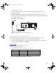
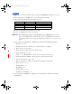
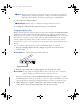
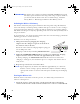

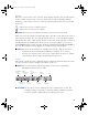
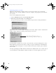

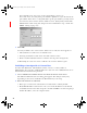
Table Of Contents
- Copyright © 2007 LifeScan, Inc. All rights reserved. No part of this publication may be reproduced, transmitted, transcribed, st...
- Disclaimer LifeScan reserves the right to change its products and services at any time to incorporate the latest technological developments. This guide is subject to change without notice.
- Trademarks OneTouch, DataLink, and SureStepPro are registered trademarks of LifeScan, Inc.
- MeterLink and Flexx are trademarks of LifeScan, Inc.
- Lantronix is a registered trademark of Lantronix.
- Windows is a registered trademark of Microsoft Corporation.
- InstallAnywhere is a registered trademark of Zero G Software, Inc.
- OneTouch® DataLink® Connection Overview 1
- OneTouch® DataLink® Sync Configuration 4
- Modem-to-Modem Configuration 9
- Serial Server/Client-to-Ethernet Configuration 10
- Serial Server/Client-to-Ethernet Configuration Using Modems 11
- Terminal Server-to-Ethernet Configuration Using Multiple Receiving Modems 13
- Connecting to the Workstation 14
- Wireless Communication 16
- Establishing Connectivity Using OneTouch® MeterLink™ Software 21
- Transferring Data 28
- Troubleshooting 33
- Specifications 39
- Glossary 41
- Index 45
- Table of Contents
- Direct Connection
- Modem Configuration
- Network Configuration
- Using This Guide
- Installing OneTouch® DataLink® Sync Software on a PC Server
- 1 Install OneTouch® DataLink® Sync on the workstation. Follow the instructions provided with the OneTouch® DataLink® Sync Installation CD.
- 2 From the PC where you wish to install OneTouch® DataLink® Sync software, use the Search/Find feature to search for the OneTouch® DataLink® workstation computer on the network.
- 3 Enter the name of the OneTouch® DataLink® workstation. The default name should be LFS_DATALINK or LFS-DATALINK.
- 4 Locate and open the DataLink Sync directory on the C drive.
- 5 Double-click install.htm.
- 6 Click Start Installer for Windows.
- 7 Click Next in the Introduction window.
- 8 Click Install to install OneTouch® DataLink® Sync software in the default directory (C:/Program Files/LifeScan/DataLink Sync). Or, if you wish to install the program in another location, click Choose and select a new directory.
- 9 Click Done in the Install Complete window.
- 10 Close the browser window.
- Connecting a OneTouch® DataLink® Connection Module to the PC Server
- Using OneTouch® DataLink® Sync Software
- Connecting a OneTouch® DataLink® Connection Module to a Sending Modem
- 1 Connect the 3-pin plug of the connection module power cord to the receptacle on the AC adapter. Then, plug the AC adapter into an AC power outlet.
- 2 Set the switches on the back of the modem as follows:
- 1
- 2
- 3
- 4
- 5
- 6
- 7
- 8
- up
- up
- down
- up
- down
- up
- down
- down
- 3 Connect the power cord from the modem to an AC power outlet.
- 4 Connect a phone cable from the modem to an analog phone jack.
- 5 Connect a phone cable from the connection module to the modem connector. Then, connect the modem connector to the modem. If th...
- 6 Turn on the modem.
- Serial Server/Client-to-Ethernet Configuration
- Connecting a OneTouch® DataLink® Connection Module to a Serial Server/Client
- 1 Connect the 3-pin plug of the connection module power cord to the receptacle on the AC adapter. Then, plug the AC adapter into an AC power outlet.
- 2 Connect a phone cable between the connection module and the serial server connector. Then, connect the serial server connector...
- 3 Connect the power cord from the serial server/client to an AC power outlet.
- 4 Connect the network patch cable from the serial server/client to the network jack or hub.
- Serial Server/Client-to-Ethernet Configuration Using Modems
- Connecting a Receiving Modem to a Serial Server/Client
- 1 Set the switches on the back of the modem as follows:
- 1
- 2
- 3
- 4
- 5
- 6
- 7
- 8
- down
- up
- up
- down
- up
- up
- down
- up
- 2 Connect the power cord from the modem to an AC power outlet.
- 3 Connect a phone cable from the modem to an analog phone jack. The jack must be for a dedicated analog phone line.
- 4 Connect the power cord from the serial server/client to an AC power outlet.
- 5 Connect the network patch cable from the serial server/client to the network jack or hub.
- 6 Connect the modem-to-serial server cable between the serial server/client and modem.
- 7 Turn on the modem.
- Terminal Server-to-Ethernet Configuration Using Multiple Receiving Modems
- Connecting a Receiving Modem to a Terminal Server
- 1 Set the switches on the back of the modem as follows:
- 1
- 2
- 3
- 4
- 5
- 6
- 7
- 8
- down
- up
- up
- down
- up
- up
- down
- up
- 2 Connect the power cord from the modem to an AC power outlet.
- 3 Connect a phone cable from the modem to an analog phone jack. The jack must be for a dedicated analog phone line.
- 4 Connect the network patch cable from the terminal server to the terminal server connector. Then, connect the terminal server connector to the modem.
- 5 Connect the power cord from the terminal server to an AC power outlet.
- 6 Connect the network patch cable from the terminal server to the network jack or hub.
- 7 Turn on the modem and terminal server.
- Connecting to the Workstation
- Connecting a OneTouch® DataLink® Connection Module to the Workstation
- 1 Connect the 3-pin plug of the connection module power cord to the receptacle on the AC adapter. Then, plug the AC adapter into an AC power outlet. If you’re connecting a OneTouch® Flexx™ meter to the workstation using a serial cable, skip this step.
- 2 Connect a phone cable from the connection module to the serial port connector. Then, connect the serial port connector to the ...
- 3 If applicable, connect the network patch cable from the workstation to the network jack.
- 4 Turn on the workstation.
- Connecting a Receiving Modem to the Workstation
- 1 Set the switches on the back of the modem as follows:
- 1
- 2
- 3
- 4
- 5
- 6
- 7
- 8
- down
- up
- up
- down
- up
- up
- down
- up
- 2 Connect the power cord from the modem to an AC power outlet.
- 3 Connect a phone cable from the modem to an analog phone jack. The phone jack must be for a dedicated analog phone line.
- 4 Connect the serial modem cable from the modem to the serial port on the workstation.
- 5 If applicable, connect the network patch cable from the workstation to the network jack.
- 6 Turn on the modem and workstation.
- Wireless Communication
- Setting Up the Wireless Unit
- 1 Connect a phone cable to the serial port connector. Then, connect the serial port connector to the workstation’s serial port.
- 2 Open a HyperTerminal session in Windows.
- 3 Click Restore Defaults on the Port Settings screen. The COM properties for the port should be:
- 4 Connect the charger to the wireless unit. Then, plug the charger into an AC power outlet.
- 5 While holding down the X key on the keyboard (ensure Caps Lock is off), connect the other end of the phone cable (from step 1) to the Setup jack on the side of the wireless unit.
- 6 Press Enter when prompted.
- Configuring Network Parameters and Channel Settings
- For a Static IP
- For DHCP
- Charging the Wireless Unit
- Reforming the Wireless Unit Battery
- 1 Charge the battery by plugging the charging adapter into the charger receptacle on the front of the wireless unit (as shown).
- 2 When the CHARGING LED illuminates steady green, unplug the charging adapter from the wireless unit and wait approximately 30 seconds.
- 3 Repeat steps 1 and 2 six consecutive times.
- Cleaning the Wireless Unit
- OneTouch® MeterLink™ Application Window
- Establishing a Connection with a Serial Server, Terminal Server, or Serial Client
- Establishing a Connection with a PC Server/Client
- Establishing a Connection with the Workstation Serial Port
- SureStepPro® Bedside Unit
- OneTouch® Flexx™ Meter
- OneTouch® MeterLink™ Event Errors
- Meter Error Messages
- Wireless Unit LED Error Conditions
- Wireless Unit
- Ethernet Connection from the PC Server
- Ethernet Connection from the Meter Location
- Ethernet Connection from the Workstation
- Connection Module
- Wireless Unit

26
For a terminal server, enter 3001–3008 (corresponding to ports 1–8).
For a serial client, select Any if the port number is dynamic or if you don’t know the
port number. If the device is configured with a specific port number, you may enter it
(1024–65535). For a wireless unit the default is 10002. (Verify with your Network
Administrator if this setting was changed. See the fourth bullet in step 3 under “For
DHCP” starting on page 18.)
3 Click OK.
An entry is added to the connection list. After a few seconds, the status appears as:
• Idle (normal for a serial server or terminal server)
• Listening (normal for a serial client other than a wireless unit)
• Connection failed (normal status for a wireless unit in power-saving mode)
Additionally, the connection event is added to the event list and the log file.
Establishing a Connection with a PC Server/Client
You must have OneTouch
®
MeterLink™ software, version 3.2 or later, and be in
Administrator Access mode to establish a PC server connection. Select Administrator Access
from the File menu and enter the password.
1 Select Add PC Server/Client Connection from the Connections menu.
The PC Server/Client Connection dialog box appears. The dialog box may vary
depending on the version of OneTouch
®
MeterLink™ you are using.
2 Enter information in each field:
• Enter up to 20 characters in the Connection name field to identify the PC.
• Click TCP/IP address and enter the static (or reserved) IP address for the PC. Or,
click Name and enter the name assigned to the PC. If DHCP is used for assigning a
variable IP address, select the computer name.
ethernet.book Page 26 Friday, October 26, 2007 1:08 PM