
User's Manual
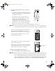
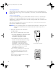
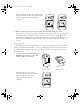
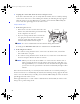
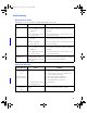
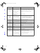
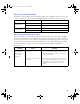
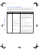
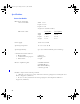
Table Of Contents
- Copyright © 2005 LifeScan, Inc. All rights reserved. No part of this publication may be reproduced, transmitted, transcribed, st...
- Disclaimer LifeScan reserves the right to change its products and services at any time to incorporate the latest technological developments. This guide is subject to change without notice.
- Trademarks OneTouch, DataLink, SureStepFlexx, and SureStepPro are registered trademarks of LifeScan, Inc.
- MeterLink is a trademark of LifeScan, Inc.
- Lantronix is a registered trademark of Lantronix.
- Windows is a registered trademark of Microsoft Corporation.
- InstallAnywhere is a registered trademark of Zero G Software, Inc.
- DataLink® Connection Overview 1
- DataLink Sync Configuration 4
- Modem-to-Modem Configuration 9
- Serial Server/Client-to-Ethernet Configuration 10
- Serial Server/Client-to-Ethernet Configuration Using Modems 11
- Terminal Server-to-Ethernet Configuration Using Multiple Receiving Modems 13
- Connecting to the Workstation 14
- Wireless Communication 16
- Establishing Connectivity Using MeterLink™ Software 20
- Transferring Data 26
- Troubleshooting 31
- Specifications 36
- Glossary 38
- Index 42
- Table of Contents
- Direct Connection
- Modem Configuration
- Network Configuration
- Using This Guide
- Installing DataLink Sync Software on a PC Server
- 1 Install DataLink Sync on the workstation. Follow the instructions provided with the DataLink Sync Installation CD.
- 2 From the PC where you wish to install DataLink Sync software, use the Search/ Find feature to search for the DataLink workstation computer on the network.
- 3 Enter the name of the DataLink workstation. The default name should be LFS_DATALINK or LFS-DATALINK.
- 4 Locate and open the DataLink Sync directory on the C drive.
- 5 Double-click install.htm.
- 6 Click Start Installer for Windows.
- 7 Click Next in the Introduction window.
- 8 Click Install to install DataLink Sync software in the default directory (C:/Program Files/LifeScan/DataLink Sync). Or, if you wish to install the program in another location, click Choose and select a new directory.
- 9 Click Done in the Install Complete window.
- 10 Close the browser window.
- Connecting a DataLink Connection Module to the PC Server
- Using DataLink Sync Software
- Connecting a DataLink Connection Module to a Sending Modem
- 1 Connect the 3-pin plug of the connection module power cord to the receptacle on the AC adapter. Then, plug the AC adapter into an AC power outlet.
- 2 Set the switches on the back of the modem as follows:
- 1
- 2
- 3
- 4
- 5
- 6
- 7
- 8
- up
- up
- down
- up
- down
- up
- down
- down
- 3 Connect the power cord from the modem to an AC power outlet.
- 4 Connect a phone cable from the modem to an analog phone jack.
- 5 Connect a phone cable from the connection module to the modem connector. Then, connect the modem connector to the modem. If th...
- 6 Turn on the modem.
- Serial Server/Client-to-Ethernet Configuration
- Connecting a DataLink Connection Module to a Serial Server/Client
- 1 Connect the 3-pin plug of the connection module power cord to the receptacle on the AC adapter. Then, plug the AC adapter into an AC power outlet.
- 2 Connect a phone cable between the connection module and the serial server connector. Then, connect the serial server connector...
- 3 Connect the power cord from the serial server/client to an AC power outlet.
- 4 Connect the network patch cable from the serial server/client to the network jack or hub.
- Serial Server/Client-to-Ethernet Configuration Using Modems
- Connecting a Receiving Modem to a Serial Server/Client
- 1 Set the switches on the back of the modem as follows:
- 1
- 2
- 3
- 4
- 5
- 6
- 7
- 8
- down
- up
- up
- down
- up
- up
- down
- up
- 2 Connect the power cord from the modem to an AC power outlet.
- 3 Connect a phone cable from the modem to an analog phone jack. The jack must be for a dedicated analog phone line.
- 4 Connect the power cord from the serial server/client to an AC power outlet.
- 5 Connect the network patch cable from the serial server/client to the network jack or hub.
- 6 Connect the modem-to-serial server cable between the serial server/client and modem.
- 7 Turn on the modem.
- Terminal Server-to-Ethernet Configuration Using Multiple Receiving Modems
- Connecting a Receiving Modem to a Terminal Server
- 1 Set the switches on the back of the modem as follows:
- 1
- 2
- 3
- 4
- 5
- 6
- 7
- 8
- down
- up
- up
- down
- up
- up
- down
- up
- 2 Connect the power cord from the modem to an AC power outlet.
- 3 Connect a phone cable from the modem to an analog phone jack. The jack must be for a dedicated analog phone line.
- 4 Connect the network patch cable from the terminal server to the terminal server connector. Then, connect the terminal server connector to the modem.
- 5 Connect the power cord from the terminal server to an AC power outlet.
- 6 Connect the network patch cable from the terminal server to the network jack or hub.
- 7 Turn on the modem and terminal server.
- Connecting to the Workstation
- Connecting a DataLink Connection Module to the Workstation
- 1 Connect the 3-pin plug of the connection module power cord to the receptacle on the AC adapter. Then, plug the AC adapter into an AC power outlet. If you’re connecting a SureStepFlexx meter to the workstation using a serial cable, skip this step.
- 2 Connect a phone cable from the connection module to the serial port connector. Then, connect the serial port connector to the ...
- 3 If applicable, connect the network patch cable from the workstation to the network jack.
- 4 Turn on the workstation.
- Connecting a Receiving Modem to the Workstation
- 1 Set the switches on the back of the modem as follows:
- 1
- 2
- 3
- 4
- 5
- 6
- 7
- 8
- down
- up
- up
- down
- up
- up
- down
- up
- 2 Connect the power cord from the modem to an AC power outlet.
- 3 Connect a phone cable from the modem to an analog phone jack. The phone jack must be for a dedicated analog phone line.
- 4 Connect the serial modem cable from the modem to the serial port on the workstation.
- 5 If applicable, connect the network patch cable from the workstation to the network jack.
- 6 Turn on the modem and workstation.
- Wireless Communication
- Setting Up the Wireless Unit
- 1 Connect a phone cable to the serial port connector. Then, connect the serial port connector to the workstation’s serial port.
- 2 Open a HyperTerminal session in Windows.
- 3 Click Restore Defaults on the Port Settings screen. The COM properties for the port should be:
- 4 Connect the charger to the wireless unit. Then, plug the charger into an AC power outlet.
- 5 While holding down the x key on the keyboard, connect the other end of the phone cable (from step 1) to the Setup jack on the side of the wireless unit.
- 6 Press Enter when prompted.
- Configuring Network Parameters and Channel Settings
- For a Static IP
- For DHCP
- Charging the Wireless Unit
- Cleaning the Wireless Unit
- MeterLink Application Window
- Establishing a Connection with a Serial Server, Terminal Server, or Serial Client
- Establishing a Connection with a PC Server/Client
- Establishing a Connection with the Workstation Serial Port
- SureStepPro Bedside Unit
- SureStepFlexx Meter
- MeterLink Event Errors
- Meter Error Messages
- Wireless Unit LED Error Conditions
- Ethernet Connection from the PC Server
- Ethernet Connection from the Meter Location
- Ethernet Connection from the Workstation
- Connection Module
- Wireless Unit

27
3 Place the bedside unit in the connection
module.
• If you have an Ethernet configuration, data is
automatically transferred to the workstation
through the network.
• If a modem is detected, the connection
module automatically dials the receiving
modem (provided the number was
downloaded to the bedside unit from the
workstation, or entered at the bedside unit).
If the line is busy, the connection module
will retry up to 20 times at 30-second intervals before it times out.
■ NOTE: If you are sharing the modem with a fax machine, do not start a data transfer
session if a fax is being sent or received—the two cannot occur simultaneously.
If the receiving modem phone number was not
downloaded to the bedside unit from the
workstation, the Enter Phone # screen appears.
Enter the phone number for the receiving
modem, then press Dial.
Messages appear on the screen indicating the
status of the connection.
The indicator light on the connection module
blinks during the transfer of data. A message
appears when data transfer is complete.
4 Remove the bedside unit from the
connection module cradle and press Cont.
■
NOTE: If the bedside unit is off when you remove it from the connection module, you
can verify that the transfer was successful by turning on the bedside unit. If an
error occurred during transfer, the following message appears after the status
screen: Last Data Transfer mm/dd/yy hh:mm Failed. Additionally, the bedside unit
displays the date and time of the last successful upload at the Main Menu.
<
Appears for modem
transfer only.
ethernet.book Page 27 Friday, December 2, 2005 4:28 PM