
User's Manual
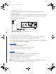
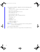
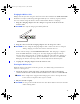
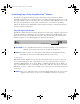
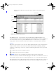
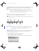
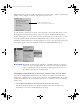
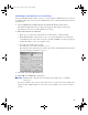
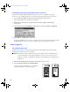
Table Of Contents
- Copyright © 2005 LifeScan, Inc. All rights reserved. No part of this publication may be reproduced, transmitted, transcribed, st...
- Disclaimer LifeScan reserves the right to change its products and services at any time to incorporate the latest technological developments. This guide is subject to change without notice.
- Trademarks OneTouch, DataLink, SureStepFlexx, and SureStepPro are registered trademarks of LifeScan, Inc.
- MeterLink is a trademark of LifeScan, Inc.
- Lantronix is a registered trademark of Lantronix.
- Windows is a registered trademark of Microsoft Corporation.
- InstallAnywhere is a registered trademark of Zero G Software, Inc.
- DataLink® Connection Overview 1
- DataLink Sync Configuration 4
- Modem-to-Modem Configuration 9
- Serial Server/Client-to-Ethernet Configuration 10
- Serial Server/Client-to-Ethernet Configuration Using Modems 11
- Terminal Server-to-Ethernet Configuration Using Multiple Receiving Modems 13
- Connecting to the Workstation 14
- Wireless Communication 16
- Establishing Connectivity Using MeterLink™ Software 20
- Transferring Data 26
- Troubleshooting 31
- Specifications 36
- Glossary 38
- Index 42
- Table of Contents
- Direct Connection
- Modem Configuration
- Network Configuration
- Using This Guide
- Installing DataLink Sync Software on a PC Server
- 1 Install DataLink Sync on the workstation. Follow the instructions provided with the DataLink Sync Installation CD.
- 2 From the PC where you wish to install DataLink Sync software, use the Search/ Find feature to search for the DataLink workstation computer on the network.
- 3 Enter the name of the DataLink workstation. The default name should be LFS_DATALINK or LFS-DATALINK.
- 4 Locate and open the DataLink Sync directory on the C drive.
- 5 Double-click install.htm.
- 6 Click Start Installer for Windows.
- 7 Click Next in the Introduction window.
- 8 Click Install to install DataLink Sync software in the default directory (C:/Program Files/LifeScan/DataLink Sync). Or, if you wish to install the program in another location, click Choose and select a new directory.
- 9 Click Done in the Install Complete window.
- 10 Close the browser window.
- Connecting a DataLink Connection Module to the PC Server
- Using DataLink Sync Software
- Connecting a DataLink Connection Module to a Sending Modem
- 1 Connect the 3-pin plug of the connection module power cord to the receptacle on the AC adapter. Then, plug the AC adapter into an AC power outlet.
- 2 Set the switches on the back of the modem as follows:
- 1
- 2
- 3
- 4
- 5
- 6
- 7
- 8
- up
- up
- down
- up
- down
- up
- down
- down
- 3 Connect the power cord from the modem to an AC power outlet.
- 4 Connect a phone cable from the modem to an analog phone jack.
- 5 Connect a phone cable from the connection module to the modem connector. Then, connect the modem connector to the modem. If th...
- 6 Turn on the modem.
- Serial Server/Client-to-Ethernet Configuration
- Connecting a DataLink Connection Module to a Serial Server/Client
- 1 Connect the 3-pin plug of the connection module power cord to the receptacle on the AC adapter. Then, plug the AC adapter into an AC power outlet.
- 2 Connect a phone cable between the connection module and the serial server connector. Then, connect the serial server connector...
- 3 Connect the power cord from the serial server/client to an AC power outlet.
- 4 Connect the network patch cable from the serial server/client to the network jack or hub.
- Serial Server/Client-to-Ethernet Configuration Using Modems
- Connecting a Receiving Modem to a Serial Server/Client
- 1 Set the switches on the back of the modem as follows:
- 1
- 2
- 3
- 4
- 5
- 6
- 7
- 8
- down
- up
- up
- down
- up
- up
- down
- up
- 2 Connect the power cord from the modem to an AC power outlet.
- 3 Connect a phone cable from the modem to an analog phone jack. The jack must be for a dedicated analog phone line.
- 4 Connect the power cord from the serial server/client to an AC power outlet.
- 5 Connect the network patch cable from the serial server/client to the network jack or hub.
- 6 Connect the modem-to-serial server cable between the serial server/client and modem.
- 7 Turn on the modem.
- Terminal Server-to-Ethernet Configuration Using Multiple Receiving Modems
- Connecting a Receiving Modem to a Terminal Server
- 1 Set the switches on the back of the modem as follows:
- 1
- 2
- 3
- 4
- 5
- 6
- 7
- 8
- down
- up
- up
- down
- up
- up
- down
- up
- 2 Connect the power cord from the modem to an AC power outlet.
- 3 Connect a phone cable from the modem to an analog phone jack. The jack must be for a dedicated analog phone line.
- 4 Connect the network patch cable from the terminal server to the terminal server connector. Then, connect the terminal server connector to the modem.
- 5 Connect the power cord from the terminal server to an AC power outlet.
- 6 Connect the network patch cable from the terminal server to the network jack or hub.
- 7 Turn on the modem and terminal server.
- Connecting to the Workstation
- Connecting a DataLink Connection Module to the Workstation
- 1 Connect the 3-pin plug of the connection module power cord to the receptacle on the AC adapter. Then, plug the AC adapter into an AC power outlet. If you’re connecting a SureStepFlexx meter to the workstation using a serial cable, skip this step.
- 2 Connect a phone cable from the connection module to the serial port connector. Then, connect the serial port connector to the ...
- 3 If applicable, connect the network patch cable from the workstation to the network jack.
- 4 Turn on the workstation.
- Connecting a Receiving Modem to the Workstation
- 1 Set the switches on the back of the modem as follows:
- 1
- 2
- 3
- 4
- 5
- 6
- 7
- 8
- down
- up
- up
- down
- up
- up
- down
- up
- 2 Connect the power cord from the modem to an AC power outlet.
- 3 Connect a phone cable from the modem to an analog phone jack. The phone jack must be for a dedicated analog phone line.
- 4 Connect the serial modem cable from the modem to the serial port on the workstation.
- 5 If applicable, connect the network patch cable from the workstation to the network jack.
- 6 Turn on the modem and workstation.
- Wireless Communication
- Setting Up the Wireless Unit
- 1 Connect a phone cable to the serial port connector. Then, connect the serial port connector to the workstation’s serial port.
- 2 Open a HyperTerminal session in Windows.
- 3 Click Restore Defaults on the Port Settings screen. The COM properties for the port should be:
- 4 Connect the charger to the wireless unit. Then, plug the charger into an AC power outlet.
- 5 While holding down the x key on the keyboard, connect the other end of the phone cable (from step 1) to the Setup jack on the side of the wireless unit.
- 6 Press Enter when prompted.
- Configuring Network Parameters and Channel Settings
- For a Static IP
- For DHCP
- Charging the Wireless Unit
- Cleaning the Wireless Unit
- MeterLink Application Window
- Establishing a Connection with a Serial Server, Terminal Server, or Serial Client
- Establishing a Connection with a PC Server/Client
- Establishing a Connection with the Workstation Serial Port
- SureStepPro Bedside Unit
- SureStepFlexx Meter
- MeterLink Event Errors
- Meter Error Messages
- Wireless Unit LED Error Conditions
- Ethernet Connection from the PC Server
- Ethernet Connection from the Meter Location
- Ethernet Connection from the Workstation
- Connection Module
- Wireless Unit

21
Connection List Report from the File menu. Print the list and keep it for
reference.
Figure 10 MeterLink software window
The MtrLink.ini file, located in the C:\Program Files\LifeScan\MeterLink directory,
contains information for all connections that have been added. Once you have established
the connection list, save a copy of the MtrLink.ini file to a safe location on a separate
storage device. In the event you need to restore the file, contact LifeScan for assistance.
Event List
Below the connection list is the event list, which displays the date, time, and description
of the recorded events for each connection. Events may include establishing, halting,
restarting, or removing a connection, as well as transferring data. Each event is preceded
by an icon.
– indicates the event is a normal occurrence.
– indicates the event is an error or failure.
■
NOTE: An error event is normal for the wireless unit in power-saving mode.
After 400 events, the software automatically replaces the oldest event with a new event on
a first-in-first-out basis. You can scroll through the list to see each event and description.
The software also creates a daily log file. The file contains a list of all events that occurred on
that day. The files are named by the date they were created, for example, 20020123.log
Event list
Connection
list
Tool bar
Status bar
Menu bar
Minimize button
ethernet.book Page 21 Friday, December 2, 2005 4:28 PM