TSC 4092A IRIG-B Autosense Fault Switch Operations and Maintenance Manual 4775 Walnut Street Suite 1B Boulder, CO 80301 www.timing.
TSC 4092A IRIG-B Autosense Fault Switch Operations and Maintenance Manual Copyright © 2005 Timing Solutions Corporation Timing Solutions is a trademark of the Timing Solutions Corporation. Other product and company names may be trademarks of their respective owners. DOC04092A Rev A Revision History Revision Description Date Approved A Initial release.
Contents 1: Introduction 1 1.1 Symbols . . . . . . . . . . . . . . . . . . . . . . . . . . . . . . . . . . . . . . . . . . . . . . . . . . . . . . . . . . . . . . . . . . . 1.2 About This Manual . . . . . . . . . . . . . . . . . . . . . . . . . . . . . . . . . . . . . . . . . . . . . . . . . . . . . . . . . . 1.2.1 Conventions . . . . . . . . . . . . . . . . . . . . . . . . . . . . . . . . . . . . . . . . . . . . . . . . . . . . . . . . . . . 1.3 4092A Overview . . . . . . . . . . . . . . . . . . . . . .
A.3 Electrical Specifications . . . . . . . . . . . . . . . . . . . . . . . . . . . . . . . . . . . . . . . . . . . . . . . . . . . . . 25 A.3.1 Environment Specifications. . . . . . . . . . . . . . . . . . . . . . . . . . . . . . . . . . . . . . . . . . . . . . 26 A.4 Physical Specifications . . . . . . . . . . . . . . . . . . . . . . . . . . . . . . . . . . . . . . . . . . . . . . . . . . . . . .
1: Introduction Note FIRST READ THIS MANUAL THOROUGHLY. This is especially true for the sections regarding Safety and Operation. 1.1 Symbols These symbols (icons) appear throughout the manual as well as on the unit itself. Symbol Note Definition This symbol means the following information is a note that gives you important information that may affect how you use the 4092A. Caution, refer to manual. Read all instructions in this manual before using this product.
1.2 About This Manual This manual tells you how to install, set up, monitor, and troubleshoot the 4092A. “Chapter 1, Introduction” on page 1 explains symbols that appear in the manual and on the unit as well as documentation conventions. The chapter also briefly describes the 4092A. “Chapter 2, Installing and Setting Up the 4092A” on page 5 contains important safety information and describes how to install the 4092A, assign a fixed IP address, select the active channel, and set the autoswitching mode.
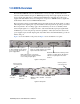
1.3 4092A Overview The TSC 4092A IRIG-B Autosense Fault Switch is a 1U (1.75") high, 19-inch, rack-mount, autosense, fault switch that accepts two IRIG-B inputs and produces eight outputs (chosen from the two inputs). The unit can be configured with redundant hot swappable AC or DC power supplies. The TSC 4092A can also be configured to accept two 1-200 kHz sinewave signals but traditionally would be used as an IRIG-B Fault Switch.
4 1: Introduction
2: Installing and Setting Up the 4092A 2.1 Safety Information Warning This unit is for INDOOR USE ONLY. It is not sealed to prevent moisture from entering the enclosure. Do not attempt to install or operate this equipment if you have not first acquired proper training. Equipment is intended for installation in an enclosed- or open-type equipment rack. Ensure that all cables are properly connected. The power cord must be easy to remove from the back.
Rack mounting screws. Screwdriver for the rack mount screws and slide, as needed. Caution Since the unit does not have a AC mains power switch, both the appliance inlet connector and the plug on the detachable power supply cord are considered to be suitable disconnect means for disconnecting the unit from the AC mains supply. If the rear of the unit is not accessible after installation in the instrument rack, you must provide a suitable external AC disconnect means for the unit.
To monitor multiple 4092A units remotely through their Ethernet connections, you must assign each unit a fixed IP address. You identify which unit is the source of an alarm by its IP address. Follow the instructions in this section to assign a unit’s IP address. Note For more detailed information, see the Xport User Manual. Section 3.3 discusses several different ways that you can assign IP addresses. Chapter 4 explains how to permanently configure the IP address.
To assign the static IP address using Telnet: 1. Telnet to the assigned address, port 9999. 2. Press Enter within five seconds to enter the setup mode. 3. Select Option 0. 4. Set the IP address and follow the on-screen instructions to save the setting. 5. Telnet to the new IP address. 6. Type I You do not need to type a carriage return or line feed.
2.5 Setting the 4092A to Autoswitch Mode As long as the 4092A is in autoswitch mode and has two input signals connected, the unit will automatically switch to the other input channel if it stops receiving a signal on the active channel. You can set the 4092A to autoswitch mode using either the switch on the front panel or remotely using the Ethernet connection. To set the 4092A to autoswitch mode from the front panel: Move the toggle switch to the center position.
10 2: Installing and Setting Up the 4092A
3: Monitoring the 4092A 3.1 Accessing the System You access the 4092A system remotely by connecting to its Command-And-Response (CNR) Port through the Ethernet connection. The CNR port (Port 10001), which uses TCP/IP, lets you input commands, displays results of the commands, and publishes alarms as they occur. When you Telnet to the CNR port, the system does not display a prompt. 3.2 Checking System Information 3.2.
Table 1 defines each status or alarm bit position.
Table 2 shows an example Telnet session of command sent to the 4092A and the response from the 4092A. Table 2: Example Telnet session Command sent 4092A response S S00000,00000 Status command 4092A set to A and autoswitch, no active alarms B ALARM22000 Make channel B active Alarm output shows change in active input; 4092A set to B with active input set to B. command S S22000,22000 Status command 4092A set to B with active input set to B. Current status should match last alarm output (ALARM22000).
Table 2: Example Telnet session (Continued) Command sent 4092A response S S02000,00000 Status command 4092A set to autoswitch with active input set to B. Input A latched fault cleared. A ALARM10000 Make channel A active Alarm output shows change in status. 4092A set to A with active input set to A. command S S10000,12000 Status command 4092A set to A with active input set to A. Current status should match last alarm output (ALARM10000). No latched alarms.
3.3 Understanding Alarm Output The 4092A automatically publishes alarms to the CNR port as they occur. The alarms appear in the format ALARMfghij where fghij is the summary status of the input and output signals. The format of the alarm status is identical to the “S” command response defined in Table 1 on page 12. Example: ALARM00003 This example shows that outputs 1 and 2 have active faults.
16 3: Monitoring the 4092A
4: Troubleshooting the 4092A Perform all of the following procedures before returning the unit for service. If the unit still appears to have a problem, call Timing Solutions Corporation and request technical support. Have the serial number of your unit ready to give to a technical representative. 4.
Table 4: INPUT SELECT LED troubleshooting INPUT SELECT LED status What it means What do to No action required. One LED solid green and one not The green LED shows the active lit channel and that the unit is in autoswitch mode, if the toggle switch is in the center position. The unlit LED shows the inactive channel. One LED flashing green and one The flashing green LED shows: not lit. The channel is the active channel. The channel was selected remotely. The unit is not in autoswitch mode.
4.4 Configuring for Input Signal and Impedance The Input Signal and Impedance settings are configured at the factory for a modulated input and low Z input and output impedance. If the signal sources have a high Z output impedance, then Caution When opening the top cover and changing the power supply settings, use proper ESD precautions. This includes ensuring that you are properly grounded before touching the internal PWA of the unit to change the jumper settings.
Caution When opening the top cover and changing the power supply settings, use proper ESD precautions. This includes ensuring that you are properly grounded before touching the internal PWA of the unit to change the jumper settings. Required for this procedure: #1 Phillips screwdriver To change the jumper setting: 1. Disconnect both power supplies from their power source. 2. Using a #1 Phillips screwdriver, remove the top cover. 3. Move the jumper one position to the left to the 2S position.
Required for this procedure: #1 Phillips screwdriver To replace a power supply: 1. Disconnect the power cord from the failed power supply. 2. Using a #1 Phillips screwdriver, remove the two screws from the failed power supply. 3. Using #1 Phillips screwdriver, remove the ground screw. 4. Slide the power supply out of the chassis. 5. Slide the new power supply into the chassis, making sure it clicks into place. 6. Replace the two screws in the power supply. 7.
22 4: Troubleshooting the 4092A
5: Warranty and Shipping Information This chapter provides information on how to contact Timing Solutions Corporation for warranty service, as well as shipping guidelines for the 4092A. 5.1 Warranty Information The 4092A carries a warranty from Timing Solutions Corporation for a period of 1 year from date of shipment.
24 5: Warranty and Shipping Information
Appendix A: Specifications A.3 Electrical Specifications Table 3 lists the electrical specifications for the 4092A. Table 3: Electrical specifications Item Specification Protection Class Class I (Grounded Type) Power Input Voltage 100–240 V ~ 50/60 Hz 0.5 A, power dissipation ~20 Watts Note: Fluctuations not to exceed ± 10% of nominal supply voltage. Power Inlet Type IEC 60320 sheet C14 AC Power Supply Cord Set 18 AWG (0.
A.3.1 Environment Specifications Warning This unit is for INDOOR USE ONLY. It is not sealed to prevent moisture from entering the enclosure. Equipment intended to be installed in an enclosed- or open-type equipment rack. Pollution Degree II per EN61010-1 Installation (Over-Voltage) Category II for transient over-voltages per EN 61010-1 Equipment suitable for continuous operation Table 4 lists the environmental specifications for the 4092A.
Glossary \n Line feed \r Carriage return CNR Command and Response DHCP Dynamic Host Configuration Protocol ESD electrostatic discharge LED light-emitting diode LSB least significant bit MSB most significant bit PDF portable document format PWA printed wiring assembly RF radio frequency TSC Timing Solutions Corporation 4092A Operations and Maintenance Manual 27
28 Glossary
Index Numerics 4092A accessing remotely 11 alarms 15 cleaning 9 command interface 11 front panel 3 installing 5 monitoring 11 overview 3 rear panel 3 required cables 5 specifications 25 unpacking 5 D DeviceInstaller software 7 dual power supplies, configuring for 19 A accessing the 4092A remotely 11 active input channel selecting from the front panel 8 selecting remotely 8 alarms checking 11 understanding 15 assigning gateway address 6 IP address 6 subnet mask 6 autoswitch mode setting from the front pan
connecting 5 O operational problems verifying 21 output connectors 3 LEDs 3 output signals connecting 5 troubleshooting 18 P packing instructions 23 panels front 3 rear 3 ports Command-And-Response 11 Ethernet 11 power connecting 5 connector 3 LED 3 specifications 25 power supplies configuring for dual 19 replacing 20 replacing fuses in 21 R replacing a fuse 21 power supplies 20 30 S safety instructions 5 setting autoswitch mode 9 shipping information 23 software version, checking 14 specifications electr