SCS100/200/400 User Guide Part Number 900-249 Revision B December 2003
Copyright & Trademark © 2003, Lantronix. All rights reserved. No part of the contents of this book may be transmitted or reproduced in any form or by any means without the written permission of Lantronix. Printed in the United States of America. Ethernet is a trademark of XEROX Corporation. UNIX is a registered trademark of The Open Group. Windows 95, Windows 98, Windows 2000, and Windows NT are trademarks of Microsoft Corp. Netscape is a trademark of Netscape Communications Corporation.
Disclaimer & Revisions Operation of this equipment in a residential area is likely to cause interference in which case the user, at his or her own expense, will be required to take whatever measures may be required to correct the interference. Note: This product has been designed to comply with the limits for a Class A digital device pursuant to Part 15 of FCC Rules. These limits are designed to provide reasonable protection against such interference when operating in a commercial environment.
Contents Copyright & Trademark ____________________________________________________________i Contacts _______________________________________________________________________i Disclaimer & Revisions ___________________________________________________________ ii Contents ______________________________________________________________________ iii 1: Introduction to the SCS Family____________________________________ 1-1 Features ____________________________________________________________________ 1-1 Protocol S
Front Panel_______________________________________________________________ 4-1 Side Panel _______________________________________________________________ 4-1 DB9 Serial Connector Pinouts____________________________________________________ 4-2 PC Card Slots ________________________________________________________________ 4-2 PC Card Slot _____________________________________________________________ 4-2 Power Connectors _____________________________________________________________ 4-2 Power Jack______________
Serial Breaks _____________________________________________________________ 6-7 Alternate Break Sequences __________________________________________________ 6-7 Modem Mode_________________________________________________________________ 6-8 Remote User Dial-Up __________________________________________________________ 6-9 Event Port Logging and Email Notification _________________________________________ 6-11 Creating an Email Site _____________________________________________________ 6-13 Dial-Out ISP Conn
Show Server______________________________________________________________ 7-6 8: Updating Software ______________________________________________ 8-1 Choosing the Right Software File _________________________________________________ 8-1 Obtaining Software ____________________________________________________________ 8-1 Via the Web ______________________________________________________________ 8-1 Via FTP _________________________________________________________________ 8-2 Reloading Software ______________
1: Introduction to the SCS Family The Lantronix SCS family of Secure Console Servers enables IT professionals to remotely and securely configure and administer servers, routers, switches, telephone equipment, or other devices equipped with a serial port. This user guide provides information about three SCS products: the SCS100, SCS200, and SCS400. These products provide the same functionality and software features but differ in hardware and port configuration options.
SCS100/200/400 User Guide 1: Introduction to the SCS Family Note: See Using Menu/Connection Commands for information on how to send intentional breaks to connected equipment.
2: The SCS100 This chapter describes the SCS100 connectors, pinouts, LEDs, and specifications. Connectors The SCS100 front panel has a male DB25 serial connector, as shown in the figure below. SCS100 Front Panel The SCS rear panel has an RJ45 Ethernet connector, a reset button, and a power connector, as shown in the figure below. SCS100 Rear Panel Note: The Reset button returns the SCS to its factory default configuration when you press and hold it during the power-up and boot process.
SCS100/200/400 User Guide 2: The SCS100 DB25 Connector Pinout The figure below shows the pin connections of the SCS100 DB25 connector. . The default serial port settings are 9600 baud, 8 bits, no parity, and 1 stop bit. DB25 Serial Connector LEDs LEDs indicate serial port activity. The SCS100 has five LEDs on the top of the unit. A red LED during boot mode typically signals an error, but red LED patterns during normal operations do not signal an error.
SCS100/200/400 User Guide 2: The SCS100 Specifications of the SCS100 Power Power Cube Adapter input output 120 VAC US; 100-240 VAC International regulated 5 VDC at 700 mA DC power input regulated 5 VDC Current 800 mA @ 5 V Power consumption 4.0 Watts max. Temperature Note: Rapid temperature changes may affect operation. Do not operate near heating or cooling devices or areas that open to the outdoors. Operating range 5° to 50° C (41° to 122° F) Storage range -40° to 66° C (-40° to 151° F) Max.
3: The SCS200 This chapter describes the SCS200 connectors, pinouts, LEDs, and specifications. Connectors The SCS200 front panel features a male DB9 serial connector, a male DB25 serial connector, and a reset button. SCS200 Front Panel DB9 Serial Port Reset Button The SCS200 rear panel has an RJ45 Ethernet connector, a power connector, and a PC card interface. The SCS200 rear panel has an RJ45 Ethernet connector, a power connector, and a PC card interface.
SCS100/200/400 User Guide 3: The SCS200 Note: The Reset button returns the SCS to its factory default configuration when you press and hold it during the power-up and boot process. Resetting to factory default will enable DHCP. Serial Connector Pinouts RS-232/RS-485 DB25 Connector The DB25 connector provides a dual RS-232/RS-485 DTE serial port. The default serial port settings are 9600 baud, 8 bits, no parity, and 1 stop bit.
SCS100/200/400 User Guide 3: The SCS200 LEDs LEDs indicate serial port and PC card activity. The SCS200 has five LEDs on the top of the unit. A red LED during boot mode typically signals an error, but red LED patterns during normal operations do not signal an error. Refer to the following tables for an understanding of LED functions: SCS200 Serial and Network LED Functions LED Function Serial Blinks green to indicate serial activity. Blinks green, or yellow to indicate network activity.
SCS100/200/400 User Guide 3: The SCS200 Specifications of the SCS200 Power Power Cube Adapter input output 120 VAC US; 100-240 VAC International 12 VDC DC power input 7-24 VDC Current 1A @ 12 V max. with PC card Power consumption 12 Watts max. Temperature Note: Rapid temperature changes may affect operation. Do not operate near heating or cooling devices or areas that open to the outdoors. Operating range 5° to 50° C (41° to 122° F) Storage range -40° to 66° C (-40° to 151° F) Max.
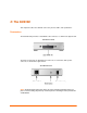
4: The SCS400 The chapter describes the SCS400 connectors, LEDs, and specifications. Connectors Front Panel The SCS400 front panel has four DB9 serial port connectors and an RJ45 Ethernet connector. SCS400 Front Panel Side Panel The SCS400 side panel has a reset button, two PC Card Slots, and two power connectors.
SCS100/200/400 User Guide 4: The SCS400 Note: The Reset button returns the SCS to its factory default configuration when you press and hold it during the power-up and boot process. Resetting to factory default will enable DHCP. DB9 Serial Connector Pinouts The following figure shows the pin connections of the SCS400 DB9 RS-232 connector. . The default serial port settings are 9600 baud, 8 bits, no parity, and 1 stop bit.
SCS100/200/400 User Guide 4: The SCS400 Screw Block Power The SCS400 also has a 9-30 VDC screw block power jack. Screw Block Power V+ VShield ground LEDs LEDs indicate serial port and PC card activity. The SCS400 has eight LEDs on the top of the unit. A red LED during boot mode typically signals an error, but red LED patterns during normal operations do not signal an error.
SCS100/200/400 User Guide 4: The SCS400 SCS400 PCC1 and PCC2 Card LED Functions LED 802.
5: Installation This chapter covers all of the steps needed to get the SCS online and working. EZWebCon is the preferred method for initial configuration, but this chapter also explains alternative methods such as the command line interface. The full command set is discussed in the SCS Reference Manual. Before you begin, note the following points: 1. The IP address must be configured before any TCP/IP functionality is available. You cannot use the web browser interface until an IP address is assigned. 2.
SCS100/200/400 User Guide 5: Installation 5. Confirm the following: a) The green Power LED lights up immediately. b) After a few seconds, the green Link LED lights up. c) After about 30 seconds, the green OK LED blinks green every two seconds. d) If you installed a PC card, the PC card LED is solid green. If the LED is any other color, see the LED section of the appropriate SCS chapter. 6. Continue with Assigning an IP Address.
SCS100/200/400 User Guide 5: Installation Select the Assignment Method 4. Select Assign Specific IP and click Next. The Assign address – IP Settings window displays. Enter IP Settings 5. Enter the IP-related settings: a) For IP Address, enter the desired IP address. b) For Subnet Mask, change the values provided only if you wish to use a mask other than the default. The default value should be correct in most cases. 6. For Gateway Address, select None. 7. Click Next.
SCS100/200/400 User Guide 5: Installation Assign IP 8. Click the Assign IP... button. 9. Wait for instructions from EZWebCon. For assistance once EZWebCon is running, refer to EZWebCon's online help. DHCP Method If DHCP is enabled on the SCS, the SCS will accept an IP address, gateway address, and subnet mask from a DHCP host. DHCP can be enabled or disabled with the following command: Set/Define Server DHCP [Enabled | Disabled] DHCP is disabled in production.
SCS100/200/400 User Guide 5: Installation 3. Reboot the SCS for the IP address to take effect. 4. If the SCS encounters an Ethernet network problem while booting, it sends an alert message to port and waits ten seconds to detect serial port activity before attempting to finish booting. If you press Enter when the alert message displays, the Boot> prompt displays. Note: For more information on Boot Configuration Program (BCP) commands, see Troubleshooting.
SCS100/200/400 User Guide 5: Installation With the ARP method, the SCS does not save the learned IP address permanently. This procedure is just a temporary measure to enable a web browser or allow an administrator to Telnet into the SCS. Once logged in, the administrator can enter the Define IP IPaddress command to make the address permanent. Changing the IP Address % telnet 192.0.1.228 7000 # access (not echoed) Lantronix Version n.n/n (yymmdd) Type Help at the `Local_>' prompt for assistance.
SCS100/200/400 User Guide 5: Installation Configuring the SCS Once you have assigned the IP address, you can configure your SCS using any of the methods discussed below: EZWebCon Method If you have just assigned the IP address using EZWebCon, you may want to continue using EZWebCon to launch the web browser interface for SCS configuration. The EZWebCon user interface allows you to set up menus and change passwords without needing to know commands.
SCS100/200/400 User Guide 5: Installation Server Configuration Window 5. Select a link from the left navigation column to configure the SCS. The root (privileged) level authorization window displays.
SCS100/200/400 User Guide 5: Installation 6. Type root in the Username field and system (default privileged password) in the Password field. (If a “remember password” popup window displays, select No and re-enter the password if necessary.) 7. Click the Login button. The desired configuration page displays. Note: For added security, change the login and privileged passwords from their default settings. You can set both passwords in the Server section of the web pages.
6: Application Setup The SCS console server allows you to remotely manage devices and equipment from anywhere on the network or from a remote dial-in through an attached modem. To use the SCS as a console server, connect its serial ports to the serial console/management ports of equipment such as UNIX servers, PBX switches, routers, network switches, or other similar devices.
SCS100/200/400 User Guide 6: Application Setup Login Banner Pages Banner Pages allow you to display text messages to users before and after authentication. Banner text information is taken from two files named prelogin.txt and postlogin.txt stored in the /ram or /flash directory on the SCS. The SCS does not store or display files stored in the /ram directory after rebooting. To implement login and logout banner text: 1. Create text files named prelogin.txt and/or postlogin.txt. 2.
SCS100/200/400 User Guide 6: Application Setup For a single global menu, the system administrator defines menus using the menu configuration web page. For multiple, group, or nested menus, the system administrator defines menu text files and uploads them to the SCS. For more information on defining menus, see the SCS Reference Manual. Creating the Menu The SCS supports a basic menu feature and an advanced menu feature.
SCS100/200/400 User Guide 6: Application Setup Connect to a device attached to the SCS with a Connect Local Port command. The port is the port name listed in the SCS, such as port_2. Connect Local Menu Entry Access a local service on the SCS with a general SCS command. Local Service Menu Entry Note: The Exit command, which only works in menu mode, allows users to return to the SCS Local> prompt.
SCS100/200/400 User Guide 6: Application Setup Using Hot Keys The SCS has default hot keys defined for Telnet connections to a port or from the menu. To change the default hot key; see the SCS Reference Manual. Ctrl+L Allows you to jump back to the menu from a port connection. Ctrl+F Allows you to jump forward to another connect session. Ctrl+B Allows you to jump backward to a previous connect session. Ctrl+Y Allows you to send a break from a Telnet or SSH connection.
SCS100/200/400 User Guide 6: Application Setup Serial Port Page 2. Click the Configure link next to the desired serial port. 3. Check the Menu checkbox. Enabling Menu Mode 4. Click the Update Port Settings button. 5. If desired, enable menu mode on other ports by repeating these steps. Using the Menu Once you have both configured the menu and enabled menu mode on a port, you can test the menu by forming a Telnet connection to that port.
SCS100/200/400 User Guide 6: Application Setup When you log into a port with menu mode enabled, you are presented with an initial login screen. Login Screen Lantronix SCSxx Version B3.6/3 (000400) Type HELP at the 'Local> ' prompt for assistance. Username> 1. Enter your user name (in this case, user) and press Enter. Login Screen, part 2 Username> user Press to continue… 2. As instructed, press Enter once more to see the actual menu. 3. Type the number of the desired menu option and press Enter.
SCS100/200/400 User Guide 6: Application Setup The table below shows some examples to help you understand how the SCS handles breaks. Examples of Alternate Break Sequences If The user Telnets to a remote network host from a local (SCS) serial port And Then The serial port is set to Break = Local The AltBreak sequence returns the user to a local (SCS) command prompt.
SCS100/200/400 User Guide Command 6: Application Setup Function Bit 0 sets response type: 0 = numeric responses 1 = text responses (default) Bit 1 sets response to unknown AT commands: 0 = do not accept unknown AT commands 1 = do accept unknown AT commands (default) Accepted and ignored Restores settings from NVR Resets modem NVR to factory settings Views current and NVR settings Writes settings to NVR Restores settings from NVR ATVx ATX[y] ATZ AT&F AT&V AT&W AT&Z The SCS holds DTR low until it forms
SCS100/200/400 User Guide 6: Application Setup Creating a User Account 2. To configure an external serial modem, attach the modem to one of the serial ports and follow these steps: a) Click the Modem link. b) Click the Configure link for the port with the attached modem. c) Select the modem type from the drop-down list. d) If you want to enable authentication, check the Authenticate Users box. e) Click the Update button. 3.
SCS100/200/400 User Guide 6: Application Setup a) Click the Modems or Back to Modems link. b) Enter the IP pool address range for remote users. Note: The IP pool range must be in the same subnet range as the SCS IP address and cannot be used by any other device on the network. If only one modem is connected to the SCS, then only one IP address is required for the pool. For this configuration, enter the same IP address in the Start and End fields. 5.
SCS100/200/400 User Guide 6: Application Setup Serial Port Settings 3. Enable port logging (also referred to as serial logging) by changing the Serial Log Size from 0 to any number between 1 and 250 Kbytes. Enabling Serial Logging and Email Events This setting creates a log file on the /ram disk in the format /ram/Port_xx.log where xx is the port name and changes the specified port to access remote. You can access the port log via ftp to the /ram directory. 4. Click the Email Events checkbox.
SCS100/200/400 User Guide 6: Application Setup Creating an Email Site Once port buffering is enabled, configure an email site for that port. An email site contains the information necessary to generate and send an email message at any system crash. Note: Email sites are not related to the sites used by the SCS to manage connections. Sites are discussed in the SCS Reference Manual. To create an Email site using the web browser interface: 1. Click the Email link under Advanced Settings. 2.
SCS100/200/400 User Guide 6: Application Setup Configuring an Email Site 5. Click the Update button to save changes. Dial-Out ISP Connection In some cases, you may require the SCS to connect to an ISP to access email or the Internet. You can configure the SCS to automatically connect to an ISP and accept a dynamically assigned IP address from the ISP. When you configure a dial-out ISP connection using the web browser interface, a site named outgoing is created.
SCS100/200/400 User Guide 6: Application Setup Configuring a Dial-Out ISP Connection 5. Click the Update button. The default route is now set to site outgoing. Note: Local Ethernet routes are not be used. To share an ISP connection with the local LAN, Network Address Translation (NAT) must be used. For more information on SCS IP routing and NAT, see the SCS Reference Manual. 6. Reboot the SCS for these changes to take effect.
SCS100/200/400 User Guide 6: Application Setup In conjunction with the Set/Define SSH Mode command, you can use the following parameters: SSH Parameters Parameter Effect Incoming (host to SCS) V1ONLY V2ONLY SCS offers only SSHv1 connections SCS offers only SSHv2 connections SCS offers both v1 and v2 and the client V1PREFER chooses V2PREFER SCS offers both v1 and v2 and the client (default) chooses Outbound (SCS to host) SCS only connects using SSHv1 SCS only connects using SSHv2 If both SSHv1 and SSH
SCS100/200/400 User Guide 6: Application Setup 2. The SCS checks to see if this user’s identity key is listed in the AUTHORIZED_KEYS (or AUTHORIZED_KEYS2) file on the SCS. If the user’s identity key is not listed in the AUTHORIZED_KEYS file on the SCS, then the authentication attempt fails. If the identity key is listed, then the process continues. 3. The SSH client then sends the private half of the user’s identity key to the SCS. 4.
SCS100/200/400 User Guide 6: Application Setup Username> Username/Password Authentication Setup New authentication keys are generated within a few minutes based on the list of authorized user public keys. A file called host_rsa_key contains the authorized users’ private identity keys. A file called host_rsa_key.pub contains the authorized users’ public identity key. As you add individual users, add their public keys to the AUTHORIZED_KEYS file on your workstation and FTP the updated file to the SCS.
SCS100/200/400 User Guide 6: Application Setup Authenticated User from Unix (OpenSSH) sshuser@UNIXHOST /# ssh -l sshuser 172.19.21.51 The authenticity of host '172.19.21.51 (172.19.21.51)' can't be established. RSA1 key fingerprint is e8:9b:7f:ee:9d:58:47:88:2e:72:a3:61:84:67:d0:d1. Are you sure you want to continue connecting (yes/no)? yes Warning: Permanently added '172.19.21.51' (RSA1) to the list of known hosts. sshuser@172.19.21.51's password: Lantronix SCS200 Version B1.
SCS100/200/400 User Guide 6: Application Setup Security Enhancements This section describes methods for increasing the security of the SCS. Incoming Security You can make the SCS into a highly secure host by turning off the FTP and HTTP services using the command: Set/Define Proto [ HTTP | FTP ] [Enabled | Disabled] Note: The web interface will no longer be available.
7: Troubleshooting This chapter discusses how you can diagnose and fix errors quickly without having to contact a dealer or Lantronix. It helps to connect a terminal to the serial port while diagnosing an error to view summary messages that may be displayed. When troubleshooting, always ensure that the physical connections (power cable, network cable, and serial cable) are secure.
SCS100/200/400 User Guide 7: Troubleshooting When you report a problem, please provide the following information: Your name, and your company name, address, and phone number Lantronix SCS model number Lantronix SCS serial number Software version (use the Show Server command to display) Network configuration, including the information from a Netstat command Description of the problem Debug report (stack dump), if applicable Status of the unit when the problem occurred (please try to include information on
SCS100/200/400 User Guide 7: Troubleshooting BOOTP Troubleshooting If the BOOTP request is failing and you have configured your host to respond to the request, check these areas: BOOTP Troubleshooting Area to Check Explanation BOOTP is in your system's /etc/services file. The SCS is in the loadhost's /etc/hosts file. The download file is in the correct directory and is world-readable. BOOTP must be an uncommented line in /etc/services.
SCS100/200/400 User Guide 7: Troubleshooting Boot Prompt Commands If the Boot> prompt appears on the serial console instead of the Local> prompt, one of two things may be wrong. Either the SCS does not have enough information to boot, or the network or flash reloading procedure has failed. If pressing Enter does not display a prompt, press any other key. The Boot> prompt should appear.
SCS100/200/400 User Guide 7: Troubleshooting Init 451 Reboots the SCS after it has been configured. If the SCS can find and load the specified software loadfile, it restarts itself with full functionality. If the loadfile is not found, the SCS attempts to reload continuously. If there is an error, or if the console's Enter key is pressed, the SCS re-enters the Boot Configuration Program. Set Server BOOTP {Enabled, Disabled} Enables or disables the sending of BOOTP queries during the boot sequence.
SCS100/200/400 User Guide 7: Troubleshooting Show Server Use this command when issuing other commands to view the current SCS setup.
8: Updating Software Choosing the Right Software File Lantronix intends to provide multiple software files for each SCS model. The software file name corresponds to the model name, as shown in the table below. Software Files Software File Name Models Supported SCS100.SYS SCS200.SYS SCS400.SYS SCS100 SCS200 SCS400 The SCS stores its software in Flash ROM. The software controls the initialization process, the operation of the SCS, and the processing of commands.
SCS100/200/400 User Guide 8: Updating Software Via FTP The SCS software resides on the Lantronix FTP server (ftp.lantronix.com). Most of these files are binary data, so the binary option must be used to transfer the files. All released files are in the pub directory. Always download the README file in the pub directory before downloading anything else; it contains a list of available software files.
SCS100/200/400 User Guide 8: Updating Software Web Interface Method This method requires an external TFTP server. You can obtain one for Windows from the Lantronix web site. 1. Open your web browser and enter the IP address of the SCS in the URL field. 2. Under Advanced Settings, select Server. 3. Specify the TFTP loadhost and verify the software file. 4. Check the Reload Firmware checkbox. 5. Click the Update Server Settings button.
SCS100/200/400 User Guide 8: Updating Software Note: For instructions on how to log into the SCS to enter these commands, see Installation. The path and filename are case-sensitive and must be enclosed in quotation marks. When attempting to boot across an IP router, configure the router to proxy-ARP for the SCS. MOP Method The firmware filename is the only parameter that the SCS needs to reload via MOP.
A: Compliance and Warranty Information Conformity Information (according to ISO/IEC Guide 22 and EN 45014) Manufacturer’s Name & Address: Lantronix 15353 Barranca Parkway, Irvine, CA 92618 USA Declares that the following product: Product Name & Model: Secure Console Server SCS100, SCS200, and SCS400 Conforms to the following standards or other normative documents: Safety: EN60950: 1992+A1, A2, A3, A4, A11 Electromagnetic Emissions: EN55022: 1998 (CISPR 22, Class A: 1993, A1: 1995, A2: 1996) IEC 1000-3-2/A14
SCS100/200/400 User Guide Compliance and Warranty Information Warranty Lantronix warrants each Lantronix product to be free from defects in material and workmanship for a period of ONE YEAR after the date of shipment. During this period, if a customer is unable to resolve a product problem with Lantronix Technical Support, a Return Material Authorization (RMA) will be issued. Following receipt of an RMA number, the customer shall return the product to Lantronix, freight prepaid.