
User's Manual
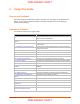
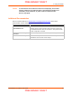
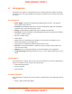
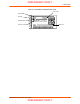
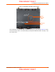
Table Of Contents
- PremierWave XC HSPA+ User Guide
- 1: Using This Guide
- 2: Introduction
- 3: Installation of PremierWave XC HSPA+
- 4: Using DeviceInstaller
- 5: Configuration Using Web Manager
- 6: Network Settings
- Network 1 (eth0) Interface Settings
- Network 1 (Link) Settings
- Network 1 (Failover)
- Network 2 (Cellular) Settings
- Network 2 (Link) Settings
- Gateway
- 7: Cellular
- 8: Action Settings
- 9: Line and Tunnel Settings
- Line Settings
- Tunnel Settings
- Serial Settings
- To Configure Tunnel Serial Settings
- Packing Mode
- To Configure Tunnel Packing Mode Settings
- Accept Mode
- To Configure Tunnel Accept Mode Settings
- Connect Mode
- To Configure Tunnel Connect Mode Settings
- Disconnect Mode
- To Configure Tunnel Disconnect Mode Settings
- Modem Emulation
- To Configure Tunnel Modem Emulation Settings
- Relay Output
- 10: Terminal and Host Settings
- 11: Services Settings
- 12: Security Settings
- 13: Maintenance and Diagnostics Settings
- Filesystem Settings
- Protocol Stack Settings
- SMTP Settings
- Diagnostics
- Threads
- Clock
- System Settings
- Discovery and Query Port
- 14: Advanced Settings
- 15: Security in Detail
- 16: Updating Firmware
- 17: Branding the PremierWave XC HSPA+
- Appendix A: Technical Specifications
- Appendix B: Compliance
- Appendix C: Technical Support
- Appendix D: Binary to Hexadecimal Conversions
- Appendix E: USB-CDC-ACM Device Driver File for Windows Hosts

PremierWave XC HSPA+ User Guide 18
3: Installation of PremierWave XC HSPA+
This chapter describes how to install the PremierWave XC HSPA+ device server. It contains the
following sections:
Package Contents
User-Supplied Items
Hardware Components
Installing the PremierWave XC HSPA+
Package Contents
The PremierWave XC HSPA+ package includes the following items:
One PremierWave XC HSPA+ device
One Power Supply 12 VDC with international adapters
Two External Antenna, SMA Connector
One RJ-45 Ethernet Straight Cat5 Cable, 1.5 meter
Quick Start Guide
User-Supplied Items
To complete your installation, you need the following items:
RS-232/422/485 serial devices and sensors that require network connectivity.
A serial cable, as listed below, for each serial device. One end of the cable must have a
female DB9 connector for the serial port.
-
A null modem cable to connect the serial port to another DTE device.
-
A straight-through modem cable to connect the serial port to a DCE device.
An available connection to your Ethernet network and an Ethernet cable.
A working AC power outlet if the unit will be powered from an AC power adapter.
SIM card
Hardware Components
Front/Top Panel
Figure 3-1 shows the top panel view of the PremierWave. Table 3-6, Table 3-7 and Table 3-8 list
and explain the behavior of the LEDs on the top panel.
LED Indicators: 2 ethernet LEDs, 1 diagnostic LED, one USB LED, one cellular status LED,
two serial activity LEDs, 5 signal strength LEDS, two of which are dual-colored.
PRELIMINARY DRAFT
PRELIMINARY DRAFT