
User Guide
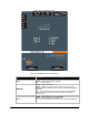

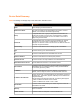


LED Description
Serial 2
GREEN – when Serial port 2 is transmitting data
AMBER – when Serial port 2 is receiving data.
OFF – when no data is being transmitted or received through Serial port
2.
USB 1
GREEN - when a USB device is connected to USB 1 Host port and is
functioning properly.
OFF- when no USB device is connected to USB 1 Host port.
USB 2
GREEN - when a USB device is connected to USB 2 Host port and is
functioning properly.
OFF- when no USB device is connected to USB 2 Host port.
Fault
RED- Blinking when Events, Errors occurred
OFF - when system functioning normally.
GSM Signal Strength
GREEN – 3 – 5 LEDs lighted. Good – Strong signal Strength
Amber – 1 – 2 bi-colored LEDs lighted. Weak signal Strength
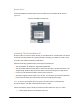
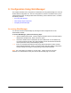
Side Panel
On the PremierWave XC Side panel, there is a 6 pin Terminal Connector for Relay, I/Os,
SMA Connector for Antenna as shown in Figure 3-8.
`
Figure 3-8 PremierWave XC Side View
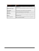
Connector Description
Relay Output Outputs Support 1A 24V
Inputs
Inputs accept voltage 0 to 30 VDC.
ON
Max 30 VDC
Min 2 VDC
OFF
Max 0.7 VDC
Min 0 VDC
Antenna Connect the provided SMA Antenna.
PremierWave XC User Guide 22