
User Manual
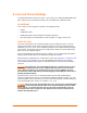


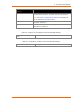

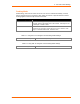
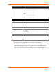
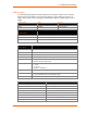
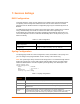
Table Of Contents
- PremierWave EN User Guide
- 1: Using This Guide
- 2: Introduction
- 3: Using DeviceInstaller
- 4: Network Settings
- 5: Line and Tunnel Settings
- 6: Configurable Pin Manager
- 7: Services Settings
- 8: Security Settings
- 9: Maintenance and Diagnostics Settings
- 10: Advanced Settings
- 11: Tunneling
- 12: Security in Detail
- 13: Updating Firmware
- A: Technical Support
- B: Binary to Hexadecimal Conversions
- C: Compliance
- D: Warranty
- E: USB-CDC-ACM Device Driver File for Windows Hosts
- Index

6: Configurable Pin Manager
PremierWave EN User Guide 38
CPM – CPs Configuration
Description
Bit : 8 7 6 5 4 3 2 1 0
: ------------------
Level : -
: ------------------
I/O : I
:-------------------
Logic :
: ------------------
Binary: x x x x x x x x 0
: ------------------
CP# : 0 0 0 0 0 0 0 0 1
:-------------------
CPM – CPs Status
Description
Name
Shows the CP number.
State
Shows the current enable state of the CP.
Value
Shows the last bit in the CP current value.
Bit
Visual display of the bitwise 32 bit placeholders for a CP.
Level
A “+” symbol indicates the CP is asserted (the voltage is high). A “-
“indicates the CP voltage is low.
I/O
Indicates the current status of the pin:
I = input
O = output
<blank> = unassigned
Logic
An “I” indicates the CP is inverted (active low).
Binary
Shows the assertion value of the corresponding bit.
CP#
Shows the CP number.
Groups
Lists the groups in which the CP is a member.
Notes:
To modify a CP, all groups in which it is a member must be disabled.
The changes to a CP configuration are not saved in FLASH. Instead, these CP
settings are used when the CP is added to a CP Group. When the CP Group is
saved, its CP settings are saved with it. Thus, a particular CP may be defined as
“Input” in one group but as “Output” in another. Only one group containing any
particular CP may be enabled at once.