MSS User Guide Part Number 900-328 Rev.
Copyright & Trademark © 2004, Lantronix. All rights reserved. No part of the contents of this book may be transmitted or reproduced in any form or by any means without the written permission of Lantronix. Printed in the United States of America. Ethernet is a trademark of XEROX Corporation. UNIX is a registered trademark of The Open Group. Windows 95, Windows 98, Windows NT, Windows ME, Windows 2000, and Windows XP are trademarks of Microsoft Corp.
Disclaimer & Revisions Operation of this equipment in a residential area is likely to cause interference in which case the user, at his or her own expense, will be required to take whatever measures may be required to correct the interference. Attention: This product has been designed to comply with the limits for a Class A digital device pursuant to Part 15 of FCC Rules. These limits are designed to provide reasonable protection against such interference when operating in a commercial environment.
Contents Copyright & Trademark ________________________________________________ i Disclaimer & Revisions _______________________________________________ ii Contents __________________________________________________________ iii 1: Introduction to the MSS Family ________________________________ 1-1 MSS Family Features _______________________________________________1-1 Protocols _________________________________________________________1-2 Terms ___________________________________________________________1-3 A
Remote Console Logins _________________________________________3-21 Incoming LAT Logins ___________________________________________3-21 Changing the Login Password________________________________________3-21 Outbound Connections _____________________________________________3-22 Logout __________________________________________________________3-22 4: Configuration _______________________________________________ 4-1 Overview _________________________________________________________4-1 Rebooting the MSS _____
Extended Service Set ID (ESSID)__________________________________4-18 Network Mode _________________________________________________4-18 Channel______________________________________________________4-18 WEP ________________________________________________________4-18 Formatting an ATA Flash Card ____________________________________4-18 Modem Cards _________________________________________________4-18 5: Using the MSS _____________________________________________ 5-18 Incoming Connections __________________
MSS VIA Connectors_______________________________________________7-18 PC Card Slot __________________________________________________7-18 Serial Connectors ______________________________________________7-18 MSS4 Connectors _________________________________________________7-18 Serial Connectors ______________________________________________7-18 MSS100 Connectors _______________________________________________7-18 DB25 Connector _______________________________________________7-18 Modem Wiring ________________
1: Introduction to the MSS Family The Lantronix MSS family of Device Servers allows you to network-enable a variety of serial devices that were not originally designed to be networked: medical devices, retail point of sale terminals, modems, industrial machinery, and more. Typically, an MSS achieves this by providing a serial port on one end and a 10BASE-T or a 10/100BASE-T Ethernet I/O port on the other end.
MSS User Guide 1: Introduction to the MSS Family Remote Configuration The MSS can be logged into and remotely configured via a network login, a Telnet login to the remote console port, EZWebCon, or a web browser connection to the MSS’ internal HTTP server. Context-Sensitive Help Context-sensitive online help is available from the CLI at any time.
MSS User Guide 1: Introduction to the MSS Family Domain Name Service (DNS) is a protocol that allows a network nameserver to translate text node names into numeric IP addresses. For WINS support, the MSS can be configured to announce itself as a WINS node. Note: MSS products support B-node functionality only The MSS also implements basic Simple Network Management Protocol (SNMP) functionality.
MSS User Guide 1: Introduction to the MSS Family The remaining chapters include 6:Troubleshooting, 7:Pinouts, and 8:Updating Software. Read them as necessary. The MSS Reference Manual, located on the CD-ROM in PDF format, provides the full MSS family command set as well as additional configuration information. Note: All IP addresses, subnet masks, and hardware addresses in this User Guide are examples only.
2: Installation This chapter covers the installation of the MSS-VIA, MSS4, and MSS100 in a network. Basic knowledge of networking installation is assumed. Read this chapter completely before continuing. MSS-VIA Installation Components The MSS-VIA front panel has a male DB9 RS-232 serial connector, a reset button, and a male DB25 serial connector supporting RS-232, RS-422, or RS-485.
MSS User Guide 2: Installation Figure 2-2. MSS-VIA Rear Panel Five LEDs are located on the top of the unit. The table below explains their functions. Table 2-1: MSS-VIA LEDs LED Function Serial Blinks green to indicate serial activity. OK Blinks green or orange/yellow to indicate network activity.
MSS User Guide 2: Installation Installation Procedure The MSS-VIA can be used to network-enable serial devices in either a wired or a wireless network, as shown in the following figures. Figure 2-3: Example Wired Network Layout Figure 2-4: Example Wireless Network Layout The MSS should be positioned close to the device it will be servicing. Since powering down the unit will terminate any active sessions, it may be desirable to place the device server in a location secure from user access.
MSS User Guide 2: Installation The following diagram shows a properly installed MSS-VIA. The numbers in the diagram refer to the installation steps in this section. Figure 2-5: MSS-VIA Connected to Serial Device and Network 1. Connect the MSS to a serial device. a) Connect one end of a serial cable to the MSS DB25 or DB9 connector. See Chapter 7:Pinouts for MSS connector pinout information.
MSS User Guide 2: Installation d) The MSS runs through a set of power-up diagnostics for approximately five seconds. The OK and Serial LEDs should show varying patterns corresponding to the test being run. Note: The Link LED should remain solid green once the unit has completed booting, assuming there is a valid connection to an Ethernet network. e) The MSS tries to obtain TCP/IP configuration information via DHCP, BOOTP, and/or RARP.
MSS User Guide 2: Installation MSS-VIA Specifications Power (power cube adaptor) Adapter: Input: 100-240 VAC Universal Power Supply with International Adapters Output: 12 VDC Max Current: 1A @ 12 V MSS-VIA power input range: 7-24 VDC Temperature Note: Rapid temperature changes may affect operation. Do not operate near heating or cooling devices or areas that open to the outdoors. Operating range: 5° to 50° C (41° to 122° F) Storage range: 40° to 66° C (-40° to 151° F) Max.
MSS User Guide 2: Installation MSS4 Installation MSS4 Components The following section discusses the specific components for the MSS4-D model. The MSS4-D front panels have four DB9 serial port connectors and an RJ45 Ethernet connector. Figure 2-7: MSS4 Front Panel All models include a reset button and two power connectors. The following figure shows an MSS side panel. Figure 2-8: MSS4 Side Panel LEDs are located on the front panel of the unit.
MSS User Guide 2: Installation Table 2-2: MSS4 LEDs LED Function Serial (1-4) Blinks green to indicate MSS serial activity. OK Blinks yellow, green, or red to indicate MSS activity. Link Glows green or yellow to indicate a wired Ethernet connection. Off: Not connected to a wired Ethernet network Green: Connected to a 10BASE-T network Yellow: Connected to either a 100BASE-T or 100BASE-FX network Installation Procedure The MSS should be positioned close to the device it will be servicing.
MSS User Guide 2: Installation 2. Connect the MSS to the network. Connect one end of a Category 5 Ethernet cable to the Ethernet network. Connect the other end of the cable to the RJ45 Ethernet port on the front of the MSS. 3. Supply power to the MSS. This can be done through either the MSS power jack or the screw terminal power connector. Do not supply power to both the power jack and the screw terminal at the same time.
MSS User Guide 2: Installation MSS4 Specifications Power (power cube adaptor) Adapter: Input: 100-240 VAC US Output: 12 VDC Current: 1.5A @ 12VDC MSS4 power input range: 9-30VDC Temperature Note: Rapid temperature changes may affect operation. Do not operate near heating or cooling devices or areas that open to the outdoors. Operating range: 5° to 50° C (41° to 122° F) Storage range: 40° to 66° C (-40° to 151° F) Max.
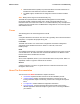
MSS User Guide 2: Installation MSS100 Installation Components The MSS100 front panel has a male DB25 serial connector. The following figure shows an MSS100 front panel. Figure 2-10: MSS100 Front Panel The MSS rear panel has an RJ45 Ethernet connector, a reset button, and a power connector. The following figure shows an MSS100 rear panel.
MSS User Guide 2: Installation Table 2-3: MSS100 LEDs LED Function Power Glows green when power is supplied to the MSS. Link Glows green while the MSS is connected properly to a 10BASE-T or 100BASE-T Ethernet network. 100 Glows green to indicate a 100 Mb Ethernet connection. OK Blinks yellow, green, or red to indicate MSS activity. Serial Blinks yellow, green, or red to indicate MSS activity.
MSS User Guide 2: Installation Figure 2-13: MSS Connected to Serial Device and Ethernet 1. Select a location. The MSS should be positioned close to the device it will be servicing. Since powering down the unit will terminate any active sessions, it may be desirable to place the device server in a location secure from user access. Also be aware of the unit’s environmental operating limits and cabling requirements. 2. Connect the MSS to an RS232-based serial device.
MSS User Guide 2: Installation Once the unit is running normally, the Power LED should be solidly lit to indicate the unit is ON, the Link LED should be solidly lit to indicate a functioning Ethernet connection, and the OK LED should blink green once every two seconds. 5. Supply power to the serial device. 6. Verify that the MSS is working. There are a few ways to check: a) Wait for approximately 30 seconds after powering the unit up.
3: Getting Started This chapter covers all of the steps needed to get the MSS online and working. There are three basic methods used to log into the MSS and begin configuration. Incoming (Remote) Logins: EZWebCon is the preferred configuration method. Users can also log into the MSS' internal HTTP server via a standard web browser. After the initial configuration, the MSS can be accessed remotely across TCP/IP networks through Telnet connections.
MSS User Guide 3: Getting Started The privileged password can be changed with the Change Server Privpass command. Specify a new password of up to six alphanumeric characters.
MSS User Guide 3: Getting Started Using ARP and Ping The ARP/ping method is available under UNIX, Windows 95/98/ME, Windows NT, Windows 2000, and Windows XP. If the MSS is connected to the LAN but has no IP address, it sets its address from the first directed IP packet it receives. Note: The ARP/ping method only works during the first two minutes of MSS operation. After two minutes, an alternate method must be used or the MSS must be rebooted.
MSS User Guide 3: Getting Started Figure 3-7: Changing the IP Address for MSS100 % telnet 192.168.0.10 Trying 192.168.0.10 Lantronix Version n.n/n (yymmdd) Type Help at the `Local_>' prompt for assistance. Enter Username> gopher Local> SET PRIVILEGED Password> system (not echoed) Local>> CHANGE IPADDRESS 192.168.0.10 Using a DHCP, BOOTP, or RARP Reply A host-based DHCP, BOOTP, or RARP server can provide information for the MSS to use to configure an IP address when the unit boots.
MSS User Guide 3: Getting Started Incoming Logins Incoming Telnet logins are enabled by default. This behavior can be changed with the Change Server Incoming command and one of the following parameters: Telnet Enables Telnet logins None Disables Telnet logins For security reasons, you may wish to disable incoming logins. If it is undesirable to disable incoming logins, the MSS can be configured to require a login password for incoming connections with the Change Server Incoming Password command.
MSS User Guide 3: Getting Started Once you have connected to the MSS, you will see the Lantronix Web Manager interface. Use the left-hand menu to navigate to subpages where you can configure important settings as well as view statistics and other device server information. Figure 3-13. Web Manager Interface EZWebCon Login and Configuration EZWebCon enables users on TCP/IP networks to log into and configure the MSS.
MSS User Guide 3: Getting Started Remote Console Logins The MSS enables users to configure the device server via a single Telnet connection to the remote console port, designated as port 7000. Connections to the console port cannot be disabled. This ensures that administrators will always be able to log into the port. To connect to the remote console port, use the Telnet command followed by the MSS IP address and the remote console port number. You will have to enter the login password.
MSS User Guide 3: Getting Started Outbound Connections When logged into the MSS, users can make basic outgoing connections using the methods described in this section. See the MSS Reference Manual on the CD-ROM for more information about incoming and outgoing connections. Note: Outgoing connections cannot be made via the same method as the incoming connection was made. Thus, if Telnet was used to enter the MSS, it cannot be used to back out.
4: Configuration Overview Certain parameters must be configured before the MSS can function on the network. Although many users will prefer to use the EZWebCon graphical user interface, this chapter explains how to configure the MSS via the command line interface. Note: Instructions for using EZWebCon are included on the distribution CD-ROM. EZWebCon also has online help to assist you with configuration.
MSS User Guide 4: Configuration Factory Defaults You should only restore factory default settings if you want to remove all custom configuration from the MSS, including password settings. To restore factory settings to the MSS: From the Local> prompt, enter the Initialize Factory command. From the Boot> prompt, enter the Flush NVR command. Press and hold the reset button down while cycling power to the unit. You must hold the reset button for at least 3 seconds after power is restored.
MSS User Guide 4: Configuration The MSS can be told which hosts are the gateways for the local network. If no gateway is specified, the MSS will listen to network broadcasts from gateways to decide which hosts are acting as gateways. The command below tells the MSS which host is the preferred gateway. Figure 4-5: Specifying a Gateway for MSS-VIA and MSS4 Local>> CHANGE SERVER GATEWAY 192.168.0.10 Figure 4-6: Specifying a Gateway Local>> CHANGE GATEWAY 192.168.0.
MSS User Guide 4: Configuration IP Security IP security allows the system administrator to restrict incoming and outgoing TCP/IP sessions and access to the serial port. Connections are allowed or denied based upon the source IP address (for incoming connections) or the destination IP address (for outgoing connections). IP security information can be added to the IP local host table. To add an entry, specify an IP address and whether to allow (Enabled) or deny (Disabled) connections.
MSS User Guide 4: Configuration The MSS will respond to queries for unknown MIBs with a not in MIB error to the requesting host. SNMP Trap Support The MSS will generate limited forms of three of the SNMP traps. Traps are sent to a host when certain events occur on the MSS. The MSS will generate a Coldstart trap when it first boots, and will send a Linkup trap when the startupfile (if any) has been read from a host and normal operation commences.
MSS User Guide 4: Configuration The MSS can be restricted to a single frame format, in which case it will not do internal routing. Two commands control this behavior: Change NetWare Routing and Change NetWare Encapsulation. Change NetWare Routing enables or disables the use of the internal network number. By default, internal routing is enabled. Note: If two or more frame types are enabled, internal routing must be enabled. To see which frame types are enabled, enter the Show NetWare command.
MSS User Guide 4: Configuration LAT Configuration Note: The following section on LAT configuration applies to the MSS100 only. Three LAT parameters can be configured for the MSS: the device server’s identification string, its service group list, and its internal circuit timer. Server Identification The MSS has a default name that it uses when announcing itself to the LAT network (mss_xxxxxx where xxxxxx represents the last six characters of its hardware address). Users can change the name.
MSS User Guide 4: Configuration RS-485 Configuration Note: This section applies to MSS models MSS-VIA and MSS4 only. The RS-485 standard allows a serial connection to be shared like a "party line." As many as 32 devices can share the multidrop network. Typically, one device is the master and the other devices are slaves. There are a few important things to note about RS-485 networking with the MSS. MSS-VIA allows for a serial connection on one port.
MSS User Guide 4: Configuration line is available to receive again. At most baud rate settings, the timing delay is typically one character length with a maximum of 1.5 character lengths. Note: For 600 baud and 4800 baud operation, the timing delay is doubled.
MSS User Guide 4: Configuration TXDrive The MSS-VIA can be configured to always drive the TX (transmit) signal, or tri-state (transmit, receive, or ignore) when not actively transmitting. The Change RS485 TXDrive command takes one of two parameters. The Always parameter sets the MSS for continuous TXDrive, both high and low. The Automatic parameter sets the MSS for TXDrive only when transmitting.
MSS User Guide 4: Configuration Figure 4-31: RS-422 Connection The MSS drives handshaking signals (CTS, RTS, DTR, DSR, and CD) at RS-232 level, and listens for those signals at RS-232 level. Serial Port Configuration The serial ports are set at the factory for 9600 baud, 8 data bits, one stop bit, and no parity. To make port settings take effect, type LOGOUT PORT n (where n is the port number). Some port settings take effect immediately upon entering the command.
MSS User Guide 4: Configuration Autostart can also be triggered by a specific input character. There is no default Autostart character; you will have to configure one. For example, when using Modem Emulation Mode you may want to use A so that Autostart will happen as soon as an AT modem command is entered. Keep in mind that when you configure an Autostart character, you can no longer use to get to the Local> prompt.
MSS User Guide 4: Configuration The examples in Figure 4-40and Figure 4-41 can be visualized as: x x x xxx xx (data) x x xx xxxxxxxx xx xxx Z xx xxxx |-------------------------------------------------------| transmit packet The complete syntax of the Change Port [Portlist] Datasend command is described in the MSS Reference Manual. Baud Rate The MSS and attached serial device, such as a modem, must agree on a speed or baud rate to use for the serial connection.
MSS User Guide 4: Configuration Flow Control Note: RTS/CTS Flow Control is not available in RS-485 mode. Both RTS/CTS (hardware) and XON/XOFF (software) flow control methods can be used on the MSS. RTS/CTS controls data flow by sending serial port signals between two connected devices. XON/XOFF controls data flow by sending particular characters through the data stream: Ctrl-Q to accept data (XON) and Ctrl-S when data cannot be accepted (XOFF).
MSS User Guide 4: Configuration Modem Control If a connection has ended, the MSS should be able to log out the port and prepare to accept a new connection. Similarly, if no connection is open, the MSS should know to ignore spurious characters from the port and only accept valid connection attempts. The MSS can do both of these when modem control is enabled. Modem control implies three things: DSRLogout enabled, meaning the MSS will log out the port when DSR is dropped.
MSS User Guide 4: Configuration Figure 4-57: Enabling DSRLogout for MSS100 Local>> CHANGE DSRLOGOUT ENABLED DTRWait Note: DTRWait is not available in RS-485 mode. Spurious characters from the modem may be interpreted as a user login, which could cause the port to be unavailable for connections. To avoid this behavior, the MSS uses the Data Transmit Ready (DTR) output line to signal the serial device that a connection is possible or acceptable.
MSS User Guide 4: Configuration Preferred Host A default host for a port can be defined using the Change Port Preferred command. The MSS attempts to use the preferred host for connections when no service name is specified in a connection command. Figure 4-63: Defining a Preferred Service for MSS-VIA and MSS4 Local>> CHANGE PORT 1 PREFERRED TCP 192.168.0.10 Figure 4-64: Defining a Preferred Service for MSS100 Local>> CHANGE PREFERRED TCP 192.168.0.
MSS User Guide 4: Configuration AP Access Point, a device that relays communications between one or more wireless devices and possibly other devices on a network. APs are usually connected to a physical network. Note: If using an AP and WEP is not enabled, set the AP to accept Open System Authentication. If WEP is enabled, set the AP to Shared Key Authentication. BSS Basic Service Set (or Cell), a group comprising one or more APs and their associated wireless devices.
MSS User Guide 4: Configuration correct for the United States; users in other countries should change it to a value appropriate for their area before attempting 802.11 operation. Figure 4-69: Setting the 802.
MSS User Guide 4: Configuration Network Mode There are two types of 802.11 networks: Ad-Hoc and infrastructure. In an Ad-Hoc network, devices communicate directly with one another on a peer-to-peer basis. In an infrastructure network (the default), several devices communicate with one or more APs, and the APs may or may not be connected to a physical Ethernet network. You must tell your MSS which type of network is present with the Change 80211 NETWORKMODE command.
MSS User Guide 4: Configuration Once WEP is enabled, you must enter a WEP key if you have not previously done so. The key can be either 40-bits or 128-bits. To enter a WEP key, use the Change 80211 WEP Key command. Each key is also assigned an index number, which is an integer between 1 and 4. To enter the index number, use the Change 80211 WEP Index command.
MSS User Guide 4: Configuration A properly installed modem card will be treated like an additional MSS serial port. If only one card is installed, it will always appear as Port 5. The Show Port and Logout Port commands will respond appropriately to the modem card ports. The modem ports will always have modem control enabled and should respond to a standard Hayes-style AT command set. However, you should not configure the modem— its default configuration will work properly with the MSS.
5: Using the MSS This chapter explains how to use the MSS once it is running. Incoming Connections (host-initiated connections) includes socket connections, using host applications, and using the code examples included on the MSS distribution CD-ROM. Interactive Connections includes manipulating sessions, making outgoing connections, and viewing device server and network information with the help of the Show commands.
MSS User Guide 5: Using the MSS TCP/IP Socket Connections Note: TCP/IP socket connections applies to MSS-VIA only. The MSS supports TCP/IP socket connections to ports 2001 and 3001. Note: Starting with firmware v3.6/8, the MSS-VIA supports socket connections to port 2002 and 3002 also (to reach the DB9 serial port). Opening a TCP session to a 300n port will form a raw TCP/IP connection to the serial port. Use a 200n port when you need Telnet IAC interpretation.
MSS User Guide 5: Using the MSS Note: Because Rlogin can bypass the normal password/login sequence and is therefore a potential security problem, it may be disabled on some hosts. It is disabled by default on the MSS. Session Control When a user makes a connection to a service on the network (via Telnet or Rlogin), a session is created. A user can have several connections to various services at once, although only one is displayed on the screen at a time. Each separate connection is a session.
MSS User Guide 5: Using the MSS The Change Port Backward Switch and Change Port Forward Switch commands define keys used to switch sessions without returning to local mode. Backward and forward switch keys must be explicitly defined.
MSS User Guide 5: Using the MSS Show IPsecurity This command shows the current TCP/IP security table, if one exists. Addresses or ranges of addresses are listed according to the kind of restrictions placed upon them. Show Ports This command displays the configuration and connection status of the serial port. Settings such as flow control, baud rate, parity, and default hosts are shown. In addition, users can view the status of DSR and DTR serial signals, port access type, and login status.
MSS User Guide 5: Using the MSS Figure 5-10: Back-to-Back MSS Connections TCP Configuration Assuming the MSS serial port parameters have been configured properly, the device servers are configured as follows for MSS-VIA and MSS4: MSS_A Local>> CHANGE PORT 1 DEDICATED TCP 192.168.0.
MSS User Guide 5: Using the MSS Setting up dedicated hosts ensures that the units will always talk to each other. Enabling Autostart for both units enables one MSS to send data to the other MSS without having to wait for a serial carriage return to start the session.. The second MSS knows exactly which other MSS to accept connections from. Finally, when Autostart is enabled, the access mode must be either Local or Dynamic (Dynamic is more flexible).
MSS User Guide 5: Using the MSS Adding Hosts The host list can include up to 16 host entries in any combination of TCP (raw, Telnet, and Rlogin) and UDP addresses. Figure 5-13: Adding Entries to the Host Table for MSS-VIA and MSS4 Local>> Local>> Local>> Local>> CHANGE PORT 1 DEDICATED HOSTLIST HOST ADD TCP 192.168.0.10:T HOST ADD UDP 192.168.0.14 LOGOUT PORT 1 Figure 5-14: Adding Entries to the Host Table for MSS100 Local>> CHANGE DEDICATED HOSTLIST Local>> HOST ADD TCP 192.168.0.
MSS User Guide 5: Using the MSS Figure 5-17. Enabling Modem Mode for MSS100 Local>> CHANGE MODEM EMULATION ENABLED Local>> CHANGE AUTOSTART CHARACTER "A" As soon as someone types an AT command, the MSS will enter modem mode and begin processing the AT commands. Modem Mode Commands The following commands are available only in modem mode—they will have no effect when typed at the Local> prompt. Command Figure 5-18: Modem Mode Commands Function AT? Help; gives list of valid AT commands.
MSS User Guide 5: Using the MSS Wiring Requirements Serial signals work differently when the MSS is in modem mode. First, the MSS will enable DTRWait and will not drive DTR until a valid connection is made with the ATDT command (see Modem Mode Commands). Second, the MSS will drop DTR whenever the TCP session is disconnected. DSRLogout is enabled implicitly. The intent is that the MSS DTR signal will be used as a simulated CD signal to the attached serial device.
6: Troubleshooting This chapter discusses how you can diagnose and fix errors quickly without having to contact a dealer or Lantronix. It helps to connect a terminal to the console port while diagnosing an error to view summary messages that may be displayed. When troubleshooting, always ensure that the physical connections (power cable, network cable, and serial cable) are secure.
MSS User Guide 6: Troubleshooting Problem/Message Error The MSS passes powerup diagnostics, but attempts to download new Flash ROM code from a network host. If the OK LED blinks rapidly, the Flash ROM code may be corrupt. Remedy Reboot the unit. If you get the same If you did not request a TFTP boot, message, you will need to reload Flash the flash ROM code is corrupt. The ROM. See Reloading Software. unit will remain in boot mode. DHCP Troubleshooting Area to Check Table 6-2.
MSS User Guide 6: Troubleshooting RARP Troubleshooting Table 6-4. RARP Troubleshooting Explanation Area to Check The MSS name and hardware The MSS name and hardware address must be in this file for the host to address in the host's answer a RARP request. /etc/ethers file The MSS name and IP address in the /etc/hosts file The MSS name and IP address must be in this file for the host to answer a RARP request. The operating system Many operating systems do not start a RARP server at boot time.
MSS User Guide 6: Troubleshooting The modem should be configured to answer the phone if incoming connections are to be supported. Generally this is done with the ats0=1 command. The modem should not be configured to answer the phone unless the MSS asserts DTR. MSS Modem control must be enabled. Using modems on ports without modem control enabled will lead to security problems. The MSS Autobaud feature should be enabled only when required.
MSS User Guide 6: Troubleshooting CHANGE DHCP {Enabled, Disabled} Enables or disables the sending of DHCP queries during the boot sequence. It is enabled by default. CHANGE HARDWARE xx-xx-xx Specifies the last three numbers of the device server's Ethernet address. The first three numbers will be supplied automatically. The Ethernet address should have been set at the factory. Setting an incorrect address could cause serious network problems.
MSS User Guide 6: Troubleshooting Technical Support If you are experiencing an error that is not described in this chapter, or if you are unable to fix the error, you may: Check our online knowledge base at www.lantronix.com/support.com E-mail us at support@lantronix.com Call us at: (800) 422-7044 Domestic (949) 453-7198 International (949) 450-7226 Fax Our phone lines are open from 6:00AM - 5:30 PM Pacific Time Monday through Friday excluding holidays.
7: Pinouts Ethernet Connector Figure 7-1: RJ45 Ethernet Connector Pinout MSS VIA Connectors PC Card Slot The MSS-VIA PC card slot accepts Type I/II PC cards. The MSS-VIA supports 802.11 wireless cards, analog modems (16550 UART types), and flash memory (PCMCIA or compact flash with PCMCIA adaptor). For the most current information on which PC card technologies are supported and which cards are compatible with the MSS-VIA, please refer to the Lantronix web site: http://www.lantronix.
MSS User Guide 7: Pinouts Figure 7-2: DB25 Serial Connector The dual DB25 port can be used for either an RS-232 connection or an RS-485 connection. Do not attempt to connect both interfaces at the same time. The MSS-VIA drives TX on both interfaces simultaneously, but only enables RX on the selected interface. For more information, see RS-485 Configuration. RS-232 DB9 Connector The MSS DB9 connector provides an RS-232 DTE serial port.
MSS User Guide 7: Pinouts Figure 7-4: DB9 RS-485 Serial Connector RS-232 DB9 Connectors The MSS4 DB9 connector also provides an RS-232 serial port. Figure 7-5: DB9 RS-232 Serial Connector MSS100 Connectors DB25 Connector The figure below shows the pin connections of the MSS DB25 connector.
MSS User Guide 7: Pinouts Modem Wiring DSR (Data Signal Ready) versus CD (Carrier Detect) By default, most modems assert CD only during a valid connection. In this case the modem’s CD pin may be wired to the Server’s DSR pin. Alternately, many modems can be configured such that DSR acts like CD. In this case, the modem’s DSR pin may be wired to the Server’s DSR pin. DTR (Data Terminal Ready) The MSS normally asserts DTR.
8: Updating Software Obtaining Software Software updates and release notes for the MSS can be downloaded directly from the Lantronix World Wide Web site (www.lantronix.com) or by FTP (ftp.lantronix.com/pub). Via the Web The latest version of MSSVIAx.SYS, MSS4.SYS, and MSS100.SYS can be downloaded from the Lantronix Web site. On the home page, http://www.lantronix.com, click on Downloads. Via FTP The MSS software resides on the Lantronix FTP server (ftp.lantronix.com/pub).
MSS User Guide 8: Updating Software attempts. The MSS will then try TFTP, NetWare, and MOP booting (in that order) provided that it has enough information to try each download method. Downloading and rewriting the Flash ROM will take approximately two minutes from the time the Initialize command is issued. If the download file cannot be found or accessed, the MSS can be rebooted with the code still in Flash ROM.
MSS User Guide 8: Updating Software The path and filename are case-sensitive and must be enclosed in quotation marks. When attempting to boot across an IP router, you must configure the router to proxy-ARP for the MSS, or use the bootgateway feature. For more information, see Change Bootgateway in the Commands chapter of the MSS Reference Manual located on the CD-ROM. NetWare The MSSVIAx.SYS file should be placed in the login directory on the NetWare file server.
MSS User Guide 8: Updating Software 8-4
A: Compliance and Warranty Information Compliance Information (According to ISO/IEC Guide 22 and EN 45014) Manufacturer’s Name & Address: Lantronix 15353 Barranca Parkway, Irvine, CA 92618 USA Declares that the following product: Product Name & Model: Device Server MSS-VIA, MSS4, and MSS100 Conforms to the following standards or other normative documents: Safety: EN60950: 1992+A1, A2, A3, A4, A11 Electromagnetic Emissions: EN55022: 1998 (IEC/CSPIR22: 1993) FCC Part 15, Subpart B, Class A IEC 1000-3-2/A14: 2
MSS User Guide A: Compliance and Warranty Information Warranty Lantronix warrants each Lantronix product to be free from defects in material and workmanship for a period of ONE YEAR. During this period, if a customer is unable to resolve a product problem with Lantronix Technical Support, a Return Material Authorization (RMA) will be issued. Following receipt of a RMA number, the customer shall return the product to Lantronix, freight prepaid.