XPress-Pro SW 94000 User Guide Part Number 900-507 Revision A May 2007
Copyright & Trademark © 2005, Lantronix. All rights reserved. No part of the contents of this book may be transmitted or reproduced in any form or by any means without the written permission of Lantronix. Printed in the United States of America. Ethernet is a trademark of XEROX Corporation. UNIX is a registered trademark of The Open Group. Windows 95, Windows 98, Windows 2000, and Windows NT are trademarks of Microsoft Corp. Netscape is a trademark of Netscape Communications Corporation.
Contents 1: Preface 6 2: Product Overview 7 Xpress-Pro SW94000 Switch___________________________________________ 7 Package Contents ___________________________________________________ 7 Product Highlights ___________________________________________________ 7 Basic Features __________________________________________________________ 7 Management Support_____________________________________________________ 8 Front Panel Display __________________________________________________ 9 Physical Ports __________
1: Preface 4: Switch Management 22 Management Access Overview ________________________________________ 22 Administration console via RS-232 serial port _________________________________ 22 Web-based browser interface _____________________________________________ 23 External SNMP-based network management application ________________________ 23 Administration Console ______________________________________________ 23 Direct Access __________________________________________________________ 23 Modem Access__
1: Preface Overview ________________________________________________________ 101 SNMP Agent and MIB-2 (RFC 1213) ___________________________________ 101 RMON MIB (RFC 1757) and Bridge MIB (RFC 1493) ______________________ 102 RMON Groups Supported _______________________________________________ 102 8: Specifications and Standards 104 A: Connector Pinouts 106 XPress-Pro SW 94000 User Guide 5
1: Preface This manual describes how to install and use the Xpress-Pro SW 94000 switch. The switch integrates full wire speed switching technology with SNMP/RMON web-based management functions. Xpress-Pro SW 94000 switch brings the answer to complicated hardened networking environments. To get the most out of this manual, you should have an understanding of Ethernet networking concepts.
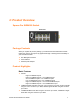
2: Product Overview Xpress-Pro SW94000 Switch Front View Package Contents When you unpack the product package, you shall find the items listed below. Please inspect the contents, and report any apparent damage or missing items immediately to your authorized reseller.
2: Product Overview Auto-negotiation for speed and duplexity on all RJ-45 ports Auto MDI/MDIX on all RJ-45 ports Full wire-speed forwarding rate Store-and-forward mechanism Back-pressure and IEEE 802.
2: Product Overview Internetworking Protocols Bridging: 802.1w Rapid Spanning Tree 802.1p/Q – GARP/GVRP IP Multicast:IGMP Snooping VLANs & IP Multicast sessions Bandwidth Control Rate Control Network Management Methods Console port access via RS-232 cable Telnet remote access SNMP agent: − MIB-2 (RFC1213) − Bridge MIB (RFC1493) − RMON MIB (RFC1757) – statistics, history, alarm and events − VLAN MIB (802.
2: Product Overview LED State Indication Steady A valid network connection established. LNK stands for LINK. 10/100TX or 100FX LNK/ACT (Green) Flashing Transmitting or receiving data. ACT stands for ACTIVITY. 100 Steady Light solid green for a port transferring at 100Mbps. (Yellow) Off The port is transferring at 10Mbps If this LED is dark. 10/100/100TX or 1000SX/LX 1000 (Green) Steady Light solid green for a port transferring at 1000Mbps.
2: Product Overview Notes: Half-duplex mode uses back pressure flow control to prevent the receiving buffer from being overrun by data from a source node. Full-duplex mode uses 802.3x flow control standard to prevent fast data traffic from overrunning slow data traffic. Auto-sensing mode is in use after auto-negotiating with the other end of the link.
2: Product Overview Whether the source MAC address or destination MAC address is to be filtered. Whether the source port ID is the same as destination port ID. If any of these conditions are met, the Xpress-Pro SW 94000 switch drops the receiving packet. Otherwise, it continues with the forwarding process described below. Forwarding During the forwarding process, the Xpress-Pro SW 94000 switch checks whether the pair is unknown.
2: Product Overview Aging The Xpress-Pro SW 94000 switch performs the aging process for the pair in the switching database. Once a pair is aged out, the SDB is modified. Spanning Tree The Xpress-Pro SW 94000 switch supports one Spanning Tree per bridged network.VLAN A virtual LAN (VLAN) is a network of computers that behave as if they are connected to the same wire, even though they may actually be physically located on different segments of a LAN.
2: Product Overview Enhanced Security Because VLANs are self-contained, only the devices within the same VLAN can communicate with each other. If a device in one VLAN wants to communicate with a device in another VLAN, the traffic must go through a router. VLAN Membership VLAN implementation allows: VLANs across multiple switches by using explicit or implicit tagging and the GARP/GVRP protocol defined in IEEE802.1p and 802.1Q. An end station’s network interface card may belong to multiple VLANs.
2: Product Overview Intra-VLAN Communication The Xpress-Pro SW 94000 switch supports intra-VLAN communication through hardware, as described in “Basic Functions” section. Inter-VLAN Communication The Xpress-Pro SW 94000 switch supports inter-VLAN communication using CPU-based routing software GVRP In addition to network management tools that allow network administrators to statically add and delete VLAN member ports, the routing switch supports GARP VLAN Registration Protocol (GVRP).
2: Product Overview The purpose of IP multicast filtering is to optimize a switched network’s performance, so multicast packets will only be forwarded to those ports containing multicast group hosts members and routers instead of flooding to all ports in the subnet (VLAN).
3: Installation This chapter gives step-by-step instructions about how to install the Xpress-Pro SW 94000 switch: Selecting a Site for the Switch As with any electric device, you should place the s Xpress-Pro SW 94000 witch where it will not be subjected to extreme temperatures, humidity, or electromagnetic interference. Specifically, the site you select should meet the following requirements: The ambient temperature should be between -34 to 74 degrees Celsius.
3: Installation Connecting to Power Redundant DC Terminal Block Power Inputs or 12VDC DC Jack: 12VDC DC Jack 1. Connect the supplied AC to DC power adapter to the receptacle on the topside of the Xpress-Pro SW 94000 switch. 2. Connect the power cord to the AC to DC power adapter and attach the plug into a standard AC outlet with the appropriate AC voltage. Redundant DC Terminal Block Power Inputs There are two pairs of power inputs for use with redundant power sources.
3: Installation 1. Connect the DC power cord to the plug-able terminal block on the Xpress-Pro SW 94000 switch, and then plug it into a standard DC outlet. 2. Disconnect the power cord if you want to shut down the Xpress-Pro SW 94000 switch. Alarms for Power Failure 1. \There are two pins on the terminal block used for power failure detection. It provides the normally closed output when the power source is active. Use this as a dry contact application to send a signal for power failure detection.
3: Installation A host system is running a terminal emulation program that supports the Kermit file transfer protocol. The host system’s hard drive has the required binary file that will be downloaded to the Xpress-Pro SW 94000 switch. Configure the system This option lets you modify any configurable parameter in the switch’s flash ROM before the Xpress-Pro SW 94000 switch system boots. Run manufacturing diagnostics This option is to download the manufacturer’s diagnostics.
3: Installation Cabling 1. First, ensure the power of the Xpress-Pro SW 94000 switch and end devices is turned off. Note: Always ensure that the power is off before any installation. 2. Prepare cable with corresponding connectors for each type of port in use. Note: To connect two regular RJ-45 ports between switches or hubs, you need a cross-over cable. 3. Consult Table 3 in previous section for cabling requirements based on connectors and speed. 4.
4: Switch Management This chapter explains the methods that you can use to configure management access to the Xpress-Pro SW 94000 switch. It describes the types of management applications and the communication and management protocols that deliver data between your management device (workstation or personal computer) and the system. It also contains information about port connection options.
4: Switch Management Web-based browser interface Advantages Ideal for configuring the Xpress-Pro SW 94000 switch remotely Compatible with all popular browsers Can be accessed from any location Most visually appealing Disadvantages Security can be compromised (hackers need only know the IP address and subnet mask) May encounter lag times on poor connections External SNMP-based network management application Advantages Communicates with the s Xpress-Pro SW 94000 witch functions at the
4: Switch Management [Default parameters] 115,200bps 8 data bits No parity 1 stop bit This management method is often preferred because you can remain connected and monitor the system during system reboots. Also, certain error messages are sent to the serial port, regardless of the interface through which the associated action was initiated. A Macintosh or PC attachment can use any terminal-emulation program for connecting to the terminal serial port.
4: Switch Management Internet Explorer If you use Internet Explorer, install the latest 4.01 Service Pack 1. This service pack makes Internet Explorer Year 2000 compliant and fixes other product-support issues. Download the 4.01 Service Pack 1 from the following location: http://www.microsoft.com/msdownload/iebuild/ie4sp1_win32/en/ie4sp1_win32.htm If the above link is unavailable, download the service pack from the Microsoft home page: http://www.microsoft.
4: Switch Management The management architecture of the Xpress-Pro SW 94000 switch adheres to the IEEE open standard. This compliance assures customers that the Xpress-Pro SW 94000 switch is compatible with, and will interoperate with other solutions that adhere to the same open standard.
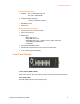
5: Menu-Driven Console Management The Xpress-Pro SW 94000 switch provides a menu-driven console interface for configuration purposes. The Xpress-Pro SW 94000 switch can be configured either locally through its RS-232 port or remotely via a Telnet session. This chapter describes how to configure the Xpress-Pro SW 94000 switch using its menu-driven console. Logging on to the switch At the screen prompt Switch Console Login: Password: Login name Enter the console interface factory default console name admin.
5: Menu-Driven Console Management Switch Management Screen Basic Management Refer to performing basic management activities. Advanced Management Refer to performing advanced management activities. Logout Highlight this option and press Enter to log out. Save Settings Highlight this option and press Enter to save the current settings and remain in the configuration program.
5: Menu-Driven Console Management Restore Default Settings Highlight this option and press Enter to restore the factory default settings. Reboot Highlight this option and press Enter to reboot. Navigating Through the Console Interface The console interface consists of a series of menu boxes. Each menu box has several options, which are listed vertically. Move the highlight to select an option as you wish; press the Enter key to activate that option.
5: Menu-Driven Console Management General Management Configurations 1. Highlight General from Basic Management screen and press . System Name is highlighted. Press if you want to change it. 2. Move to highlight Contact and press if you want to change it. 3. Move to highlight Location and press if you want to change it. 4. Move to highlight admin Password and press if you want to change it. 5. Move to highlight guest Password and press if you want to change it.
5: Menu-Driven Console Management LAN Port Configurations 1. Highlight LAN Port from Basic Management screen and press . 2. Speed & Flow Control is highlighted. Press if you want to set speed or flow control on port. 3. Move to highlight each port and press to configure individually. 4. Port Setting Options screen appears. Highlight Speed & Flow Control and press .
5: Menu-Driven Console Management 5. For Line Speed, move to highlight a desired setting from Speed Options and press . Note: In the Speed Options, HD denotes half-duplex and FD denotes full-duplex. 6. Press to previous screen. Highlight Flow Control and press . 7. For Flow Control, move to highlight a desired setting from the Flow Cntl Options and press .
5: Menu-Driven Console Management 8. Press to a previous screen as shown in step 3. 9. For Admin. Control, move to highlight Up or Down from Admin Status Options. 10. The port is set as Admin Down to stop TX/RX transmission. 11. To allow TX/RX transmission on the port, move to highlight Up from the options in step 9. 12. Press to a previous screen as shown in step 1. 13. Move to highlight Physical Address to view physical port address.
5: Menu-Driven Console Management 14. Press to return to Basic Management screen when completed. Console Port Configurations 1. Move to highlight Console Port from Basic Management screen. 2. Baud Rate is highlighted. Press if you want to change the current console baud rate. 3. Move to highlight Flow Control and press if you want to change the current flow control method. 4. Move to highlight Modem Control and press to decide a console modem connection, Disabled or Enabled.
5: Menu-Driven Console Management Performing Advanced Management Activities Advanced management activities consist of L2 Switching DataBase / IP Networking / Bridging / Static Filtering / Rapid Spanning Tree / SNMP / Other Protocols / Port Trunking / Port Mirroring / QoS Setup / File Transfer. To Perform Advanced Management Activities: 1. Highlight Advanced Management from Switch Management screen and press . The Advanced Management screen appears: 15.
5: Menu-Driven Console Management Other Protocols View and change GVRP and IGMP settings. Port Trunking Assign a range of ports to trunking groups. Port Mirroring Mirror one port to Port 1. qos setup Specify Quality of Service parameter. File Transfer Send files using the TFTP or Kermit protocol. L2 Switching DataBase VLAN & PVID Perspective There are three types of private VLAN ports: promiscuous, isolated, and community.
5: Menu-Driven Console Management Community VLAN used by a group of community ports to communicate among themselves and transmit traffic to outside the group via the designated promiscuous port.
5: Menu-Driven Console Management For example: Primary VLAN Isolated VLAN Isolated VLAN Community VLAN Community VLAN VLAN ID Promiscuous port Isolated port Community ports 2 2 3,4 5,6,7,8 3 2 3 4 2 4 5 2 5,6 6 2 7,8 1. Create the primary VLAN and bind the promiscuous port, isolated port(s), and community ports to the primary VLAN. 2. Create the isolated VLAN(s) and bind the promiscuous port and isolated port(s) to the isolated VLAN(s). 3.
5: Menu-Driven Console Management Note: Default VLAN: The IEEE802.1Q standard defines VLAN ID #1 as the default VLAN. The default VLAN includes all the ports as the factory default. The default VLAN’s egress rule restricts the ports to be all untagged, so it can, by default, be easily used as a simple 802.1D bridging domain. The default VLAN’s domain shrinks as untagged ports are defined in other VLANs. 3. Press and [+] on keypad to enter New VLAN Settings. Enter new VLAN ID and VLAN name.
5: Menu-Driven Console Management 5. Move to highlight a suitable option from Port Options and press , e.g. Untagged Ports. 6. From Select Untagged Ports, press to select All Ports or move to highlight each port individually and press . Similar procedure when you select Tagged Ports and Forbidden Ports in step 4. Note: If you added untagged ports and want to now add tagged ports or forbidden ports, or vice versa, repeat steps 4 and 5. 7.
5: Menu-Driven Console Management 11. Move to highlight VLAN Activities and press to view or search activity information. 12. Return to Step 9 Move to highlight VLAN Settings and press . The screen appears as shown in Step 3 for adding or deleting switch ports. 13. Highlight the VLAN & PVID Perspective and press .
5: Menu-Driven Console Management 14. Highlight the PVID Settings and press to apply PVIDs to the ports. 15. Highlight the port and press to enter PVID to the port. 16. Highlight the VLAN & PVID Perspective and press . 17. Highlight the TPID and press . 18. Press to enter TPID value. IP Multicast Group Perspective 1. Move to highlight L2 Switching DataBase from Advanced Management screen and press . 2.
5: Menu-Driven Console Management 2. Enter a MAC address to view characteristics information, corresponding VLANs, and corresponding ports in the switching database. Port Perspective 1. Move to highlight Port Perspective from L2 Switching DataBase screen, and press . You can view Per Port VLAN activities and Per Port statistics and set Per Port MAC Limit here. 2. Per Port VLAN Activities is highlighted. Press . 3. Move to highlight a port and press . (E.g.
5: Menu-Driven Console Management 4. View or search by MAC address individually. 5. Press to return to a previous screen as shown in step 1. 6. Move to highlight Per Port Statistics and press . 7. Move to highlight a port and press . (E.g. select Port 1 to view corresponding VLAN Activities.) Press [R] to reset counter for this port.
5: Menu-Driven Console Management 8. Move to highlight Per Port MAC Limit and press . 9. Move to highlight a port and press .
5: Menu-Driven Console Management IP Networking 1. Move to highlight IP Networking from Advanced Management screen and press . 2. Highlight IP Settings from IP Networking and press . The screen shows a list of VLAN IDs, IP addresses, subnet masks, proxy ARPs currently defined. 3. Move to highlight the row that contains the parameters you want to change, and then press .
5: Menu-Driven Console Management 4. Highlight ARP Table from IP Networking and press . 5. Press and [+] on keypad to enter Internet Address and Physical Address in the Static ARP Specifications. 6. Highlight Default Gateway from IP Networking and press . 7. Enter Default Gateway and Metric in the Default Route Specifications.
5: Menu-Driven Console Management 8. Highlight DHCP Gateway Settings from IP Networking and press . Ping Settings 1. Move to highlight Ping from IP Networking and press . 2. Move to highlight Host and press .
5: Menu-Driven Console Management 3. Enter 4 decimal bytes (dot separated) as the IP address to ping. 4. Move to highlight Count and press . 5. Specify a packet count number from 1 to 999, or type 0 for an infinite packet count. Press . 6. Move to highlight Size and press . 7. Specify a packet size from 0-1500. Press . 8. Move to highlight Timeout and press . 9. Specify a timeout value from 1-999. Press . 10.
5: Menu-Driven Console Management 2. Move to highlight Source or Destination MAC addresses Out-Filters for static filtering, and press . 3. Press [+] on keypad to add a specific MAC address to be filtered. Press [-] to delete a specific MAC address from being filtered.
5: Menu-Driven Console Management Press [S] to search through current list of MAC addresses in the static filtering database. The static filtering database maximum capacity is 64. Note: * No precautionary message appears before you delete a specific MAC address from being filtered. * Be sure you want to delete it before doing so. MAC Address In-Filters 1. Move to highlight MAC Address In-Filters from Static Filtering screen, and press . 2. Move to highlight a port and press . 3.
5: Menu-Driven Console Management Rapid Spanning Tree Protocol 1. Move to highlight Rapid Spanning Tree from Advanced Management screen, and press . 2. Move to highlight Spanning Tree Configurations if you want to change Spanning Tree Protocol Configurations. 3. Press to enter Spanning Tree Options. Decide to have it Disabled or Enabled. 4. Move to highlight Bridge Priority and press .Type a decimal number for the bridge priority and press . 5.
5: Menu-Driven Console Management 9. Move to highlight Tx Hold Count and press .Type a decimal number for the Tx Hold Count. 10. Move to highlight Path Cost Default and press .Choose 16-bit or 32-bit and press . 11. Move to highlight Spanning Tree Port States if you want to change per port administration status, and press . 12. Move to highlight a port if you want to Enable or Disable its administration status, and press . Spanning Tree Path Costs 1.
5: Menu-Driven Console Management 2. Move to highlight All Ports or each port individually, and press . For new priority value, type a decimal number from 0-240, and press . A low value gives the port a greater likelihood of becoming a Root port. Protocol Migration 1. Move to highlight Protocol Migration if you want to change the Protocol Migration per port, and press . 2. Move to highlight each port individually, and press to Enable or Disable Protocol Migration. Edge Port 1.
5: Menu-Driven Console Management 2. Move to highlight each port individually, and press to Enable or Disable Edge Port Setting. Point To Point Link 1. Move to highlight Point To Point Link if you want to change the Point To Point Link Options per port, and press . 2. Move to highlight each port individually, and press to choose Enable, Disable, or Auto Point To Point Link. SNMP Functions 1. Move to highlight SNMP from Advanced Management screen, and press .
5: Menu-Driven Console Management 2. Move to highlight SNMP and press . Decide to have it Disabled or Enabled. 3. Move to highlight Get Community Name and press . Enter text and press . 4. Move to highlight Set Community Name and press .Enter text and press . 5. Move to highlight Trap Community Name 1 and press . Enter text and press . Repeat to specify up to four more trap community names. 6. Move to highlight Trap Host 1 IP Address and press .
5: Menu-Driven Console Management Other Protocols 1. Move to highlight Other Protocols from Advanced Management screen, and press . 2. Move to highlight GVRP and press . Decide to have it Disabled or Enabled. 3. Move to highlight Mode and press . Decide to have it Disabled or set in either Passive or Active mode.
5: Menu-Driven Console Management 4. Move to highlight Concentration Mode and press . Decide to have it Disabled or Enabled. Port Trunking 1. Move to highlight Port Trunking from Advanced Management screen, and press . 2. Move to highlight a trunk group to which you want to assign ports, and press to enter Select Range.
5: Menu-Driven Console Management 3. Press to select each trunk port. 4. Press when completed with selecting ports. Port Mirroring 1. Move to highlight Port Mirroring from Advanced Management screen, and press .
5: Menu-Driven Console Management 2. Press to enter Port Mirroring Options. 3. Press to enter Mirror To Options, listing the ports that can be mirrored to. 4. Move to highlight the port you want to mirror to and press . 5. Press to enter Mirror From Options, listing the ports that can be mirrored from. 6. Move to highlight the port you want to mirror from and press . 7. Move to select Mirror Mode.
5: Menu-Driven Console Management 2. Move to highlight Global Setting and press . 3. Move to highlight QoS Status and press . Move to highlight to enable or disable QoS Status and press . 4. Move to highlight Diffserv Expedite Forwarding and press . Move to highlight to enable or disable Diffserv Expedite Forwarding and press . 5. Move to highlight ToS/VLAN Tag Preference and press . Highlight the VLAN Tag or ToS then press . 6.
5: Menu-Driven Console Management 2. Move to highlight User Define Port, Well-Known Port, or Range Port and press . 3. Move to highlight the appropriate port and press . 4. Press when completed. VLAN 1. Move to highlight VLAN and press to specify the QoS VLAN priority. 2. Move to highlight any VLAN Priority Index and press . Move to highlight Drop Priority or Transmit Priority and press in the VLAN Priority Setting screen. 3. Press when completed. ToS 1.
5: Menu-Driven Console Management Tx Queue Setting 1. Move to highlight Tx Queue Setting and press . 2. Press when completed. Fixed Priority 1. Move to highlight Fixed Priority and press to specify the Fixed Priority. 2. Move to highlight any port in the ToS Priority screen and press . Move to Fixed Drop Priority, Transmit Priority, or Priority. 3. Press when completed.
5: Menu-Driven Console Management Rate Control 1. Move to highlight Rate Control and press to specify rate control parameters. 2. Move to highlight Rate Control, or Port Number and press . 3. Press when completed. File Transfer The TFTP protocol is used to upload software to the switch and download software from the switch. A VLAN with the proper IP address and routing path to the TFTP server must be configured for the switch to access the specified TFTP server. 1.
5: Menu-Driven Console Management 2. Move to highlight Receive File Via TFTP and press . 3. If the default File Name is not the one you intend to receive, press . Type the name of the file you intend to receive and press . 4. Move to highlight IP Address and press . Type the IP address from where the file will be obtained. 5. Press when completed. A dialog box appears to ask if you want to transfer file now. 6. Highlight [Yes] and press to start file transfer.
5: Menu-Driven Console Management 8. If the default File Type is not the one you intend to send, press . Select the file type you intend to send and press . 9. Repeat steps 4-6. 10. In File Transfer screen obtained via console port, move to highlight Receive File Via Kermit and press . A dialog box appears to ask if you want to transfer file now. 11. Move to highlight [Yes] and press to start file transfer. Otherwise, highlight [No] and press to deny it. 12.
5: Menu-Driven Console Management 16. Press to a previous screen. Logout To log out, highlight [Logout] from [Switch Management] screen and press . Please remember to save settings you have changed before you log out. Save Settings To save the current settings and remain in the configuration program, highlight [Save Settings] from [Switch Management] and press .
6: Web-Based Browser Management The s Xpress-Pro SW 94000 witch provides a web-based browser interface for configuring and managing the Xpress-Pro SW 94000 switch. This interface allows you to access the Xpress-Pro SW 94000 switch using a preferred web browser. This chapter describes how to configure the Xpress-Pro SW 94000 switch using its webbased browser interface. Logging on to the switch Switch IP Address In your web browser, specify the IP address of the Xpress-Pro SW 94000 switch.
6: Web-Based Browser Management Understanding the Browser Interface The web browser interface provides three point-and-click buttons at the upper field of the screen for configuring and managing the Xpress-Pro SW 94000 switch. In addition, you can click any port on the Xpress-Pro SW 94000 switch image to view the Xpress-Pro SW 94000 switch’s current speed, duplex, and activity status. The Basic Setup/General parameters appear at the lower field of the screen.
6: Web-Based Browser Management Saving Setting 1. Click Saving Setting to save your configuration settings. 2. When you click it, a message asks ”Are you sure you want to save setting? ”, click OK to save it or Cancel to abort it. Receive File Via TFTP 1. Click Receive File Via TFTP on the File display. Notes: The TFTP protocol is used to upload software to the Xpress-Pro SW 94000 switch.
6: Web-Based Browser Management 4. Click Receive Now!. Send File Via TFTP 1. Click Send File Via TFTP on the File display. 1. For File Name, choose the file you intend to send. 2. For IP Address, type the IP address you intend to send to. 3. Click Send Now!. Reboot 1. Click Reboot on the File display. 2. When you click it, a message asks ”Are you sure you want to save setting? ”, click OK to save it or Cancel to abort it. 3. Click Logout on the File display. 4.
6: Web-Based Browser Management General Management Configuration 1. Click General and the screen shows the Basic Setup/General parameters. The screen here is the same when you first access the Xpress-Pro SW 94000 switch browser interface. 2. Click in System Name text box on the field of Basic Setup/General. 3. Type a system name if it is blank, or replace the current system name with a new one. 4. Click in Location text box on the field of Basic Setup/General. 5.
6: Web-Based Browser Management 7. To allow or prevent the Xpress-Pro SW 94000 switch from rebooting when a fatal error is detected, click the appropriate option from Reboot-On-Error drop-down menu. 8. To enable or disable access to the Xpress-Pro SW 94000 switch management program via Telnet, click the appropriate option from Remote Telnet Login dropdown menu. 9. Click Update Setting. A confirmation window appears. LAN Ports Configuration 1.
6: Web-Based Browser Management 4. In the Port column, click the port you want to configure. E.g. click Port 1. 5. Click the drop-down menu under Admin Setting, decide to disable or enable it. Note: Disable places the port in DOWN state. In this state, packets cannot be switches to and from the port. Enable places the port in UP state. In this state, packets can be switched to and from the port. 6.
6: Web-Based Browser Management Note: Auto allows the Xpress-Pro SW 94000 switch to automatically ascertain whether or not to use flow control. Disable: turns off flow control at all times. Enable: turns on flow control at all times. 8. Click Update Setting when completed. A confirmation window appears. Note: For your convenience, click the LEDs on the image of the Xpress-Pro SW 94000 switch and view its current speed, duplex, and link activity. Console Port Configuration 1.
6: Web-Based Browser Management Performing Advanced Setup Activities To perform Advanced Setup Activities: 1. Click the Advanced Setup button at the upper field of the main display, the menu options appear. MAC Address Management 1. From the Advanced Setup menu, point to MAC Address Management to view VLANs and their associated MAC addresses. Per VLAN View 1. Click Per VLAN View first and click on the port that you want to view. 2. Close the VLAN Activities window when finished viewing.
6: Web-Based Browser Management 3. From the Advanced Setup menu as shown in Step 1, point to MAC Address Management. Click Individual MAC View. 4. Click in the Enter MAC Address text box and type the MAC address that you want to view. Then click on the Get Information button. 5. Close the Individual MAC View window when finished viewing.IP Networking 6. To access the IP networking parameters, click the Advanced Setup button, and Point to IP Networking from the selection menu. IP Settings 1.
6: Web-Based Browser Management 2. In the VLAN ID column, click a VLAN ID whose settings you want to view and/or change. 3. To change the IP Address, click in the text box and type a new address. Alternatively, you can use the Delete IP button to delete the IP address. Note: No precautionary message appears before you delete the IP address. * Be sure you want to delete it before doing so.* The IP address is not deleted until you click Update Setting. 4.
6: Web-Based Browser Management 6. To change the BOOTP selection, click a value from the drop-down list. 7. To change the Proxy ARP selection, click a value from the drop-down list. 8. When you finished with these selections, click Update Setting. A confirmation window appears. Click to close the confirmation window. Default Gateway 1. Click Default Gateway to access Default Gateway settings. 2. To set the Default Gateway, click in the text box and type a new Default Gateway. 3.
6: Web-Based Browser Management Port Perspective 1. To access Port Perspective, click the Advanced Setup button, and then click Port Perspective from the selection menu. 2. To access Port Perspective VLAN Activities, click the Per Port VLAN Activities from the selection menu. Click a port to view Port Perspective VLAN Activities.
6: Web-Based Browser Management 3. To access Per Port Statistics, click the Per Port Statistics from the selection menu. Click a port to view statistic data. Bridging 1. To access bridging parameters, click the Advanced Setup button, and then click Bridging from the selection menu.
6: Web-Based Browser Management 2. Click the drop-down list for Disabled (No Aging) or Set Aging Time. 3. Click the text box and type a decimal number as bridge aging period in seconds. 4. Click the drop-down list for No Flooding, Controlled Flooding, Unlimited Flooding. 5. Click the text box and type a decimal number as flood limit in packets per second. 6. Click the drop-down list for Set Limit or Unlimited. 7. Click the text box and type a decimal number as broadcast limit in packets per second. 8.
6: Web-Based Browser Management Source MAC Address Filters 1. Click Source MAC Address Filters. 2. Click Add MAC Addr button to add a source MAC address for static filtering. 3. The Static Source MAC Filter window appears. Click in the Source MAC Address Filter text box and type a unique MAC source address you want to add. Then click the Add button. 4. A confirmation window appears. Close the confirmation window. 5.
6: Web-Based Browser Management 6. The Delete Source MAC Address window appears. Click the Select a MAC Address drop-down list and select the source MAC address you want to delete. Then click the Delete button. 7. A confirmation window appears. Close the confirmation window. Destination MAC Address Filters 1. Click the Advanced Setup button, and point to Static MAC Filters in the selection menu. Click Destination MAC Address Filters. 2.
6: Web-Based Browser Management MAC Address In-Filters 1. Click MAC Address In-Filters. Click a port to add or delete In-Filters MAC Address. 2. Click Add MAC Addr button to add an In-Filters MAC Address.
6: Web-Based Browser Management 3. The Add New MAC Address In-Filter window appears. Click in the MAC Address In-Filter text box and type a unique MAC source address you want to add. Then click the Add button. 4. A confirmation window appears. Close the confirmation window. 5. If you no longer need an In-Filters MAC Address, click Delete MAC Addr button to delete it in step 2. 6. The Delete MAC Address In-Filter window appears.
6: Web-Based Browser Management VLAN & PVID Perspective 1. To view the VLAN configuration information, click the Advanced Setup button, and point to VLAN & PVID Perspective in the selection menu. VLAN Setting 1. Click VLAN Setting. 2. Click on a VLAN ID whose VLAN configuration you want to change. 3. The VLAN Setting window appears. Add or delete switch ports for VLAN ID 1. For each switch, the port options include Tagged Ports, Untagged Ports, or Forbidden Ports.
6: Web-Based Browser Management 4. Click on the Add VLAN button to create a new VLAN. 5. The Add a New VLAN window appears. 6. Click in the VLAN ID textbox and specify a new VLAN ID number from 2~4094. 7. Click in the VLAN Name textbox and type a name for this newly created VLAN. 8. Assign switch ports to this VLAN. For each switch, the port options include Tagged Ports, Untagged Ports, or Forbidden Ports. 9. Click Add Now! button. 10. Click on the Delete VLAN button to delete a VLAN.
6: Web-Based Browser Management 11. The Delete VLAN window appears. 12. Click the drop-down menu to select a VLAN ID, which you want to delete. 13. Click the Delete button. Note: * No precautionary message appears before you delete a VLAN. * Be sure you want to delete it before doing so. TPID 1. Click TPID. TPID Setting 1. Click TPID Setting. 2. Click in the TPID textbox and type an address for TPID. PVID Setting 1. Click PVID Setting.
6: Web-Based Browser Management 2. Click on a Port to assign VLAN ID to this port. RSTP (Rapid Spanning Tree Protocol) 1. To view the rapid spanning tree protocol parameters, click the Advanced Setup button, and point to RSTP in the selection menu. 2. To view and/or change the RSTP configurations, click Configurations from the above screen.
6: Web-Based Browser Management 3. For Spanning Tree Protocol, specify whether you want to have it Disabled or Enabled by clicking the drop-down list. 4. For Bridge Priority, click in the text box and type a decimal number between 0 and 65535. 5. For Hello Time, click in the text box and type a decimal number between 1 and 10. 6. For Max Age, click in the text box and type a decimal number between 6 and 40. 7. For Forward Delay, click in the text box and type a decimal number between 4 and 30. 8.
6: Web-Based Browser Management 2. In the Port column, click the port whose RSTP Port Configuration you want to change. 3. For Port STP Status, specify whether the Port STP Status is Enable or Disable by clicking the drop-down list. 4. For Priority, click in the text box and type a decimal number as a new priority value. 5. For Admin. Path Cost, click in the text box and type a decimal number as a new admin. path cost value. 6.
6: Web-Based Browser Management 9. Click Update Setting. A confirmation window appears. Close the confirmation window. SNMP 1. To view and/or change all SNMP-related information, click the Advanced Setup button, and click SNMP in the selection menu. The SNMP Configurations window appears. As shown below, the factory-default Community Name value is public. 2. For SNMP, specify whether it is Disabled or Enabled by clicking the drop-down list. 3.
6: Web-Based Browser Management 14. For Topology Change Trap, specify whether it is Disabled or Enabled by clicking the drop-down list. 15. Click Update Setting when completed. A confirmation window appears. Close the confirmation window. Other Protocols 1. To enable or disable the GVRP and/or IGMP protocols, click the Advanced Setup button, and click Other Protocols in the selection menu. 2. For GVRP, specify whether it is Disabled or Enabled by clicking the drop-down list. 3.
6: Web-Based Browser Management The Trunk Group 1 window appears. 2. Click the drop-down menu to select a desired range. 3. Click to assign ports to the trunk group. QoS 1. To use the Xpress-Pro SW 94000 switch’s QoS capability, point to the Advanced Setup button, and point to QoS in the selection menu.
6: Web-Based Browser Management Global Setting 1. Point to Advanced Setup, point to QoS, and Click Global Setting. 2. Use the QoS drop-down list to enable or disable QoS. 3. Use the DiffServ Expedite Forwarding drop-down list to specify whether you want to enable or disable DiffServ Expedite Forwarding. 4. Use the ToS/VLAN Tag drop-down list to select the priority you want to use. 5. Use the ToS for Xmint drop-down list to select the Bits of ToS you want to use. 6.
6: Web-Based Browser Management 8. Click Update Setting when completed. A confirmation window appears. Click to close the confirmation window. Logic Port 1. Point to Advanced Setup, point to QoS, and Click Logic Port. 2. Point to Advanced Setup, point to QoS, point to Logic Port, and click User Define Port, Well-Known Port, or Range Logic Port. 3. Click Update Setting when completed. A confirmation window appears. Click to close the confirmation window. VLAN 1.
6: Web-Based Browser Management Type of Service 1. Point to Advanced Setup, point to QoS, and Click Type of Service. 2. For each Type of Service priority, use the right drop-down list to select a Transmit Priority for that Type of Service and use the right drop-down list to select a High or Low Drop Priority for that Type of Service. 3. Click Update Setting when completed. A confirmation window appears. Click to close the confirmation window. Tx Queue Setting 1.
6: Web-Based Browser Management 2. Click a port number under Port. Use the Fixed Transmit Priority, Drop Priority, and Priority drop-down list to select a different priority for the port. 3. Click Update Setting when completed. A confirmation window appears. Click to close the confirmation window. Rate Control 1. Point to Advanced Setup, point to QoS, and Click Rate Control. 2. Use the Rate Control drop-down list to enable or disable rate control. 3. Click a port number under Port.
6: Web-Based Browser Management Mirror To 1. Click 1 or 2 in the Index column. In the Mirror To column, select a “mirror to” port by clicking the drop-down list. Data traffic will be mirrored to this port. 2. In the Mirror From column, select a “mirror from” port by clicking the drop-down list. Data traffic will be mirrored from this port. 3. In the Mirror Mode column, specify whether the “mirrored from” port will be receiving or transmitting data by clicking the drop-down list. 4.
7: SNMP & RMON Management This chapter describes the Xpress-Pro SW 94000 switch’s Simple Network Management Protocol (SNMP) and Remote Monitoring (RMON) capabilities. Overview RMON is an abbreviation for the Remote Monitoring MIB (Management Information Base). RMON is a system defined by the Internet Engineering Task Force (IETF) document RFC 1757, which defines how networks can be monitored remotely.
7: SNMP & RMON Management Authentication failure Rising alarm Falling alarm Topology Alarm MIB-2 defines a set of manageable objects in various layers of the TCP/IP protocol suites. MIB-2 covers all manageable objects from layer 1 to layer 4 and, as a result, is the major SNMP MIB supported by all vendors in the networking industry. The Xpress-Pro SW 94000 switch supports a complete implementation of SNMP Agent and MIB-2.
7: SNMP & RMON Management The dot1dStatic Group – contains objects that describe the entity’s destination-address filtering status. This group is applicable to any type of bridge which performs destinationaddress filtering.
8: Specifications and Standards Specification Description Xpress-Pro SW 94000 10/100BaseTX auto-negotiating ports with RJ-45 connectors, 100BaseFX fiber ports, 10/100/1000BaseTX auto-negotiating ports with RJ-45 connectors, and 1000BaseSX/LX fiber ports combination IEEE 802.3 10BaseT IEEE 802.3u 100BaseTX/FX IEEE 802.3ab 1000BaseT IEEE 802.
8: Specifications and Standards Standards ESD Standard (IEC 61000-4-2) Radiated FRI Standards (IEC 61000-4-3) Burst Standards (IEC 61000-4-4) Surge Standards (IEC 61000-4-5) Induced (Conducted) RFE Standards (IEC 61000-4-6) Magnetic Field Standards (IEC 61000-4-8) Voltage Dips Standards (IEC 61000-4-11) Environmental Test Standards: Vibration Resistance (IEC 60068-2-6) Shock (IEC 60068-2-27) Free Fall (IEC 60068-2-32) XPress-Pro SW 94000 User Guide 105
A: Connector Pinouts Pin Arrangement of RJ45 Connectors The following table lists the pinout of 10/100BaseT/TX ports. Pin Regular Ports Uplink port 1 2 3 4 5 6 7 8 Output Transmit Data + Output Transmit Data Input Receive Data + NC NC Input Receive Data NC NC Input Receive Data + Input Receive Data Output Transmit Data + NC NC Output Transmit Data NC NC The following table lists the pinout of 10/100/1000BaseTX ports.