UDS2100 User Guide Part Number 900-448 Revision D January 2009
Copyright & Trademark © 2007, 2008 Lantronix. All rights reserved. No part of the contents of this book may be transmitted or reproduced in any form or by any means without the written permission of Lantronix. Printed in the United States of America. Ethernet is a trademark of XEROX Corporation. UNIX is a registered trademark of The Open Group. Windows 95, Windows 98, Windows 2000, and Windows NT are trademarks of Microsoft Corp. Netscape is a trademark of Netscape Communications Corporation.
Contents 1: Using This Guide 7 Purpose and Audience _______________________________________________ 7 Chapter Summary ___________________________________________________ 7 Additional Documentation _____________________________________________ 8 2: Introduction 9 Applications ________________________________________________________ 9 Application Examples ________________________________________________ 9 Protocol Support ___________________________________________________ 11 Additional Features ________
Contents Serial Port Connection ___________________________________________ 37 Exiting Setup Mode _________________________________________________ 38 6: Setup Mode: Server Configuration Server Configuration (Option 0)________________________________________ IP Address ________________________________________________________ Set Gateway IP Address _____________________________________________ Netmask: Number of Bits for Host Part __________________________________ Set DNS Server IP Address ________________
Contents SNMP Community Name _________________________________________ Disable Telnet Setup_____________________________________________ Disable TFTP Firmware Update ____________________________________ Disable Port 77FE (Hex) __________________________________________ Disable Web Server _____________________________________________ Disable Web Setup ______________________________________________ Disable ECHO Ports _____________________________________________ Enable Enhanced Password ______________________
Contents Conversion Table _______________________________________________ 80 Scientific Calculator______________________________________________ 81 D: Warranty 82 E: Compliance and Disclaimer 83 Index 85 Figures Figure 2-1. Serial Tunneling Example _____________________________________ Figure 2-2. Direct TCP/IP or Redirector Configuration ________________________ Figure 2-3. Sample Hardware Address ____________________________________ Figure 3-1.
1: Using This Guide Purpose and Audience This guide provides the information needed to configure, use, and update the UDS2100 device server. It is for system administrators and those responsible for installing and maintaining the UDS. Chapter Summary Table 1-1. Chapter Summary The remaining chapters in this guide Chapter Description 2: Introduction Describes the main features of the UDS and the protocols it supports.
1: Using This Guide Chapter Description B: Alternative Ways to Assign an IP Address Provides detailed information about using DHCP, AutoIP, BOOTP ARP, and Telnet to assign an IP address. Error! Reference source not Provides instructions for converting binary values to found. Error! Reference source hexadecimal. not found. D: Warranty E: Compliance and Disclaimer Documentation Update For the latest revision of this product document, please check our online documentation at www.lantronix.
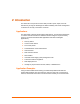
2: Introduction The UDS2100 is a 2-port device server that provides a quick, simple, and costeffective way to bring the advantages of data accessibility and remote management to devices not currently connected to a network. Applications The UDS family of Device Servers allows serial devices, such as those listed below, to connect and communicate over Ethernet networks using the IP protocol family (TCP for connection-oriented stream applications and UDP for datagram applications).
2: Introduction Figure 2-1. Serial Tunneling Example The Com Port Redirector software included on the product CD simplifies the integration process by extending the functionality of COM-port-based Windows™ applications. Virtual COM ports, mapped to remote device servers on the network, can replace direct serial connections. Figure 2-2.
2: Introduction Protocol Support The UDS uses the Internet Protocol (IP) for network communications and the Transmission Control Protocol (TCP) to assure that no data is lost or duplicated and that everything sent to the connection arrives correctly at the target. Supported protocols include: ARP, UDP, TCP, ICMP, Telnet, TFTP, AutoIP, DHCP, HTTP, and SNMP for network communications. TCP, UDP, and Telnet for connections to the serial port. TFTP for firmware updates.
2: Introduction Product Information Label The product information label on the underside of the unit contains the following information about your specific unit: Bar code Serial number Product ID (name) Product description Hardware address (also referred to as the Ethernet or MAC address) The first three bytes of the hardware address are fixed and read 00-20-4A, identifying the unit as a Lantronix product. The fourth, fifth, and sixth bytes are unique numbers assigned to each unit. Figure 2-3.
3: Getting Started This chapter describes how to get your UDS up and running in the shortest possible time. Package Contents Verify and inspect the contents of the UDS2100 package using the following list. If any item is missing or damaged, contact your place of purchase immediately.
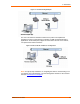
3: Getting Started Installing the UDS Figure 3-1. UDS2100 Connected to Serial Device and Network To install the unit: To install the unit, complete the following steps in order. Refer to the numbers in the previous figure. 1. Connect a serial device to your unit. See 2: Introduction for more information about what kinds of device attachments the unit supports. 2. Connect an Ethernet cable to the 10/100 port. 3. Supply power to your unit using the power supply that was included in the packaging.
3: Getting Started Required Information Before configuring the UDS, have the following information available: Hardware Address Take note of the unit’s hardware address (also known as the Ethernet or MAC address). It is on the product label, in the format: 00-20-4a-XX-XX-XX, where the XXs are unique numbers assigned to the product Hardware Address: 00-20-4a-_____-_____-_____ IP Address The UDS must have a unique IP address on your network. This address references the specific unit.
3: Getting Started Assigning the IP Address: DeviceInstaller This chapter covers the steps for getting the UDS2100 device server online and for viewing its current configuration. Note: DeviceInstaller online Help provides more detailed information on using DeviceInstaller. Installing DeviceInstaller To use the DeviceInstaller utility, first install it from the product CD. 1. Insert the product CD into your CD-ROM drive. The Lantronix UDS2100 DeviceInstaller window displays. 2.
3: Getting Started 7. Select the device from the main window list and select Ping from the Tools menu. The Ping Device dialog box shows the IP address of the selected unit. 8. From the Tools menu, click the Ping button. The results display in the Status window. Click the Clear Status button to clear the window so you can ping the device again.
3: Getting Started Table 3-1. Current Configuration Setting Description Name Configurable field. A name that identifies the UDS2100. Double-click the field, type in the value, and press Enter to complete. This name is not visible on other PCs or laptops using DeviceInstaller. Group Configurable field. A group name to categorize the UDS2100. Double-click the field, type in the value, and press Enter to complete. This group name is not visible on other PCs or laptops using DeviceInstaller.
3: Getting Started Setting Description Telnet Port Non-configurable field. Displays the UDS2100’s port for telnet sessions. Web Enabled Non-configurable field. Permits configuration through WebManager. Web Port Non-configurable field. Displays the UDS2100’s port for WebManager configuration. Maximum Baud Rate Supported Non-configurable field. Displays the UDS2100’s maximum baud rate. Note: The UDS2100 may not currently be running at this rate. Firmware Upgradeable Non-configurable field.
3: Getting Started Note: Alternatively, to open Web Manager, open your web browser and enter the IP address of the unit. To configure the unit using a Telnet session: 1. Click the Telnet Configuration tab. The Setup Mode window displays. 2. Press Enter within 5 seconds. 3. Continue with step 4 in 5: Configuration via Telnet or Serial Port (Setup Mode). Assigning the IP Address: Serial Port Login To assign the IP address and other network settings using a serial connection: 1.
4: Configuration Using Web Manager You must configure the unit so it can communicate on a network with your serial device. For example, you must set the way the unit will respond to serial and network traffic, how it will handle serial packets, and when to start or close a connection. The unit’s configuration is stored in nonvolatile memory and is retained without power. You can change the configuration at any time. The unit performs a reset after you change and store the configuration.
4: Configuration Using Web Manager Figure 4-1. Lantronix Web Manager The main menu is in the left pane of the Web Manager window. Network Configuration The unit’s network values display when you select Network from the main menu. The following sections describe the configurable parameters on the Network Settings page.
4: Configuration Using Web Manager Figure 4-2. Network Settings Automatic IP Address Configuration An IP address can be assigned automatically. You then enter related network settings. Note: Network Mode is Wired Only. To assign an IP address automatically: 1. On the main menu, click Network. 2. Select Obtain IP address automatically. 3. Enter the following (as necessary): BOOTP Select Enable to permit the Bootstrap Protocol (BOOTP) server to assign the IP address from a pool of addresses automatically.
4: Configuration Using Web Manager UDS2100 unit automatically. Enable is the default. AutoIP Select Enable to permit the UDS2100 to generate an IP in the 169.254.x.x address range with a Class B subnet. Enable is the default. DHCP Host Name Enter the name of the host on the network providing the IP address. Note: Disabling BOOTP, DHCP, and AutoIP (all three checkboxes) is not advised as the only available IP assignment method will then be ARP or serial port. 4.
4: Configuration Using Web Manager 1. On the main menu, click Network. 2. Enter the following (as necessary): Auto Negotiate With this option, the Ethernet port auto-negotiates the speed and duplex with the hardware endpoint to which it is connected. This is the default. If this option is not selected, complete the fields that become available: Speed: The speed of data transmission. The default setting is 100 Mbps. Duplex: The direction of data transmission. The default setting is Full. 3.
4: Configuration Using Web Manager Server Configuration Telnet Password Enter the password required for Telnet access. Retype Password Re-enter the password required for Telnet access. Advanced ARP Cache Timeout (secs) When the unit communicates with another device on the network, it adds an entry into its ARP table. ARP Cache timeout defines the number of seconds (1-600) before it refreshes this table.
4: Configuration Using Web Manager Figure 4-4. Hostlist Settings 2. Enter or modify the following fields: Retry Settings Retry Counter Enter the value for the number of times the UDS2100 should attempt to retry connecting to the host list. The default setting is 3. Retry Timeout Enter the duration (in seconds) the UDS2100 should abandon attempting a connection to the host list. The default setting is 250. Host Information Host Address Enter or modify the host’s IP address.
4: Configuration Using Web Manager 1. From the main menu, click Serial Settings for either Channel 1 or Channel 2 to display the Serial Settings page for the selected channel. Figure 4-5. Channel Serial Settings 2. In the available fields, enter the following information: Channel 1 Disable Serial Port When selected, disables communication through the serial port. The serial port is enabled by default.
4: Configuration Using Web Manager Data Bits Indicates the number of bits in a transmitted data package. The default setting is 8. Parity Checks for the parity bit. The default setting is None. Stop Bits The stop bit follows the data and parity bits in serial communication. It indicates the end of transmission. The default setting is 1. Pack Control Enable Packing Select to enable packing on the UDS2100. Two firmware-selectable packing algorithms define how and when packets are sent to the network.
4: Configuration Using Web Manager Flush Output Buffer (Network to Serial) With Active Connect Select Yes to clear the output buffer with a connection that is initiated from the device to the network. The default setting is No. With Passive Connect Select Yes to clear the output buffer with a connection initiated from the network to the device. The default setting is No. At Time of Disconnect Select Yes to clear the output buffer when the network connection to or from the device is disconnected.
4: Configuration Using Web Manager Figure 4-6. TCP Connection Settings 2. In the available fields, enter or modify the following information: Connect Protocol Protocol From the drop-down menu, select TCP. Connect Mode: Passive Connection Accept Incoming Select Yes to accept incoming connections. The default setting is Yes. Password Required Determines whether a password is required for an incoming passive connection. This field is not available when a password is set for Telnet mode.
4: Configuration Using Web Manager sequence). Connect Mode: Active Connection Active Connect Select None (default) to disable Active Connect. Otherwise, indicate the connection type from the drop-down list: With Any Character: Attempts to connect when any character is received from the serial port. With Active Mdm Ctrl In: Accepts external connection requests only when the Modem Control In input is asserted.
4: Configuration Using Web Manager one name. When this option is enabled, the unit also reacts to the end of record (EOR) and binary options, which can be used for applications such as terminal emulation to IBM hosts. Use Hostlist If this option is set to True, the device server scrolls through the host list until it connects to a device listed in the host list table. Once it connects, the unit stops trying to connect to any others.
4: Configuration Using Web Manager Figure 4-7. UDP Connection Settings Connect Protocol Protocol Select UDP from the drop-down menu. Datagram Mode Datagram Type Configures the remote IP or network broadcast address and the remote port. Enter 01 for directed or broadcast UDP. The default setting is 00. Accept Incoming Select Yes to accept incoming UDP datagrams. The default setting is Yes. Endpoint Configuration Local Port Enter the local port number.
4: Configuration Using Web Manager 4. On the main menu, click Apply Settings. Apply Settings 1. To save and apply the configuration changes to the device server, click the Apply Settings button. Note: Clicking OK on each page does not change the configuration on the device. OK tells the UDS2100 what changes to use; Apply Settings makes the changes permanent and reboots the UDS2100. Apply Factory Defaults 1. Click the Apply Defaults button to set the device server back to the default settings.
5: Configuration via Telnet or Serial Port (Setup Mode) You must configure the unit so it can communicate on a network with your serial device. As an alternative to using a web browser, as described in the previous chapter, you can use the following procedures remotely or locally: Use a Telnet connection to configure the unit over the network. Use a terminal or terminal emulation program to access the serial port locally. The series of prompts at which you enter configuration settings is called Setup Mode.
5: Configuration via Telnet or Serial Port (Setup Mode) To establish a Telnet connection: 1. From the Windows Start menu, click Run and type the following command, where x.x.x.x is the IP address, and 9999 is the unit’s fixed network configuration port number: Windows: telnet x.x.x.x 9999 UNIX: telnet x.x.x.x:9999 2. Click OK. The following information displays. Figure 5-1. MAC Address 3. To enter Setup Mode, press Enter within 5 seconds.
5: Configuration via Telnet or Serial Port (Setup Mode) Exiting Setup Mode To exit setup mode: You have two options: To save all changes and reboot the device, select option 9 Save and exit from the Change Setup menu. All values are stored in nonvolatile memory. To exit the configuration mode without saving any changes or rebooting. select option 8 Exit without save from the Change Setup menu.
6: Setup Mode: Server Configuration This chapter explains how to configure the network settings. Note: Current values display in parentheses. Server Configuration (Option 0) The unit’s basic network parameters display when you select Server configuration (option 0). The IP Address, Set Gateway IP Address, and Netmask fields display the current values. Figure 6-1. Network Settings IP Address If DHCP is not used to assign IP addresses, enter the IP address manually.
6: Setup Mode: Server Configuration segment as the unit. The gateway address must be within the local network. The default setting is N (No), meaning the gateway address has not been set. To set the gateway address, type Y and enter the address. Set Gateway IP Address (N) ? Y Gateway IP addr (000) (000) (000) (000)_ Netmask: Number of Bits for Host Part A netmask defines the number of bits taken from the IP address that are assigned for the host part.
6: Setup Mode: Server Configuration DHCP Name If a DHCP server has automatically assigned the IP address and network settings, you can discover the unit by using the DeviceInstaller network search feature or Monitor Mode (see 10: Monitor Mode). Note: When you enter Monitor Mode from the serial port with network connection enabled and issue the NC (Network Communication) command, you see the unit’s IP configuration. There are three methods for assigning DHCP names to the unit.
7: Setup Mode: Channel Configuration This chapter explains how to configure the serial ports. Notes: Current values display in parenthesis. You must enter some values in hexadecimal notation. (See Error! Reference source not found. Error! Reference source not found..) Channel 1 (Option 1) Note: The procedure is the same for Channel 2 (Option 2). Select Channel 1 (option 1) from the Change Setup menu to define how the serial port responds to network and serial communications.
7: Setup Mode: Channel Configuration I/F (Interface) Mode The Interface (I/F) Mode is a bit-coded byte entered in hexadecimal notation. The default setting is 4C. I/F Mode (4C) ? _ The following table displays available I/F Mode options: Note: All bit positions in the table that are blank represent “don’t care” bits for that particular option, which can be set to either a 0 or 1 value. Table 7-1.
7: Setup Mode: Channel Configuration Table 7-3. Flow Control Options Flow Control Option Hex No flow control 00 XON/XOFF flow control 01 Hardware handshake with RTS/CTS lines 02 XON/XOFF pass characters to host 05 Port Number The setting represents the source port number in TCP connections. It is the number that identifies the channel for remote initiating connections. Port No (10001) ? _ The default setting for Port 1 is 10001.
7: Setup Mode: Channel Configuration Table 7-5.
7: Setup Mode: Channel Configuration b) Response Character Response A single character is transmitted to the serial port when there is a change in connection state: C = connected, D = disconnected, N = host unreachable. This option is overridden when the Active Start Modem Mode or Active Start Host List is in effect. Default setting is Nothing (quiet). This option is overridden when the Active Start Modem Mode or Active Start Host List is in effect. Default setting is Nothing (quiet).
7: Setup Mode: Channel Configuration If an IP address does not follow the first command string character (which is "C"), the subsequent character string is interpreted as the host name and domain to be used in DNS lookup. This character string can include a destination port number as well. The port number can be preceded by either a forward slash (/) or a colon ( : ). Figure 7-2. Manual Connection Address Example Command String Result if remote IP is 129.1.2.3 and remote port is 1234 C121.2.4.
7: Setup Mode: Channel Configuration Figure 4-7. Hostlist Option To enable the hostlist: 1. Enter a Connect Mode of 0x20 (2X), where X is 1-5. 1=start with any character, 2=with active Modem Control In, 3=with carriage return, 4=manual connection, 5=autostart. The menu shows you a list of current entries already defined in the product. 2. To delete, modify, or add an entry, select Yes. If you enter an IP address of 0.0.0.0, that entry and all others after it are deleted. 3.
7: Setup Mode: Channel Configuration When the UDP option is in effect, the unit never attempts to initiate a TCP connection because it uses UDP datagrams to send and receive data. e) Modem Mode In Modem (Emulation) Mode, the unit presents a modem interface to the attached serial device. It accepts AT-style modem commands and handles the modem signals correctly. Normally, there is a modem connected to a local PC and a modem connected to a remote machine.
7: Setup Mode: Channel Configuration Message Meaning RING n.n.n.n. A remote device, having IP address n.n.n.n, is connecting to this device. Numeric Response 0 OK 1 Connected 2 Ring 3 No Carrier 4 Error Received commands must begin with the two-character sequence AT and be terminated with a carriage return character. The unit ignores any character sequence received not starting with AT, and only recognizes and processes single AT-style commands.
7: Setup Mode: Channel Configuration Modem Mode Command Function ATDTx.x.x.x:pppp ATDTx.x.x.x Makes a connection to an IP address (x.x.x.x) and the remote port number defined within the unit. ATD0.0.0.0 Forces the unit into Monitor Mode if a remote IP address and port number are defined within the unit. ATD or ATDT Forces the unit into Monitor Mode if a remote IP address and port number are not defined within the unit. ATDx.x.x.x Makes a connection to an IP address (x.x.x.
7: Setup Mode: Channel Configuration Auto Increment Source Port Auto increment source port (N) ? _ Y (Yes) auto increment the source port. The UDS2100 increments the port number used with each new connection. Remote IP Address This is the destination IP address for an outgoing connection. Remote IP Address : (000) (000) (000) (000)_ Note: This option does not display when Hostlist is enabled from the ConnectMode prompt (see Connect Mode on page 44 for more information).
7: Setup Mode: Channel Configuration Disconnect Mode Option 7 6 5 4 Disable hard disconnect 3 2 1 0 1 State LED off with connection (4) Disconnect with EOT (^D) (5) 1 1 (1) The Telnet Com Port Control feature is used in conjunction with Com Port Redirector. The UDS sends the "Terminal Type" upon an outgoing connection. (2) A password is required for a connection to the serial port from the network. (3) The TCP connection closes even if the remote site does not acknowledge the disconnection.
7: Setup Mode: Channel Configuration packet count low. The alternate packing algorithm minimizes the packet count on the network and is especially useful in applications in a routed Wide Area Network (WAN). Adjusting parameters in this mode can economize the network data stream. Pack control settings are enabled in Flush Mode. Set this value to 00 if you do not need specific functions.
7: Setup Mode: Channel Configuration Note: A transmission might occur if status information needs to be exchanged or an acknowledgment needs to be sent. DisConnTime (Inactivity Timeout) Use this parameter to set an inactivity timeout. The unit drops the connection if there is no activity on the serial line before the set time expires. Enter time in the format mm:ss, where m is the number of minutes and s is the number of seconds. DisConnTime (00:00) ?: To disable the inactivity timeout, enter 00:00.
8: Setup Mode: Advanced Settings Expert Settings (Option 5) Note: You can change these settings using Telnet or serial connections only, not on the Web Manager. Caution: Changing the expert settings can drastically affect the performance and access to the product. These settings should only be changed by an experienced network administrator. Select 5 to configure expert settings. Figure 8-1.
8: Setup Mode: Advanced Settings Monitor Mode at bootup This option allows you to disable all entries into Monitor Mode during startup, except for the ‘xxx’ sequence. This prevents entry using yyy, zzz, xx1, and yy1 key sequences (only during the bootup sequence). The default for Monitor Mode at bootup is N (No). (See 10: Monitor Mode.) Monitor Mode @ bootup : enabled HTTP Port Number This option allows the configuration of the web server port number. The valid range is 1-65535.
8: Setup Mode: Advanced Settings Figure 8-2. Security Settings Disable SNMP This setting allows you to disable the SNMP protocol on the unit for security reasons. The default setting is N (No). Disable SNMP (N) ? _ SNMP Community Name The SNMP Community Name is a required field for NMS to read or write to a device. Enter a string of 1 to 13 characters. The default setting is public.
8: Setup Mode: Advanced Settings Disable Port 77FE (Hex) Note: If you choose to disable this option, keep in mind that disabling both Telnet Setup and Port 77FE will prevent users from accessing the setup menu from the network. Port 77FE is a setting that allows DeviceInstaller, Web Manager, and custom programs to configure the unit remotely. You may wish to disable this capability for security purposes.
8: Setup Mode: Advanced Settings Channel 1 and Channel 2 Configuration Defaults Baudrate 9600 I/F Mode 4C (1 stop bit, no parity, 8 bit, RS-232C) TCP port number 10001 on Channel 1 10002 on Channel 2 Connect Mode C0 (always accept incoming connection; no active connection startup) Hostlist retry counter 3 Hostlist retry timeout 250 (msec) Start character 0x0D (CR) All other parameters 0 Expert Settings Defaults TCP Keepalive time in s 45 ARP Cache timeout in s 600 Disable Monitor Mode @
9: Firmware Upgrades Obtaining Firmware You can obtain the most up-to-date firmware and release notes for the unit from the Lantronix web site (www.lantronix.com) or by using anonymous FTP (ftp.lantronix.com). Reloading Firmware There are several ways to update the unit's internal operational code (*.ROM): using DeviceInstaller (the preferred way), using TFTP, or using the serial port. You can also update the unit's internal Web interface (*.COB) using TFTP or DeviceInstaller.
9: Firmware Upgrades Figure 9-1. TFTP Window After the firmware has been loaded and stored, which takes approximately 8 seconds to complete, the unit performs a power reset. Using TFTP: Command Line Interface To download new firmware from a computer: 1. Enter the following from a TFTP command line interface: tftp –i put The following examples demonstrate the TFTP command sequence to download the .rom file and the .cob file: tftp –i 192.168.1.
9: Firmware Upgrades 6. For Firmware File, click the Browse button and go to the location where the firmware file resides. Note: Make sure the UDS2100 on which you are recovering firmware is connected to this selected port on your PC. 7. Click OK to download the file. 8. When prompted, reset the device. Status messages and a progress bar at the bottom of the screen show the progress of the file transfer. When the file transfer completes, the message “Successful, Click OK to Close” displays. 9.
10: Monitor Mode Monitor Mode is a command-line interface used for diagnostic purposes. There are two ways to enter Monitor Mode: locally using the serial port or remotely using the network. Entering Monitor Mode Using the Serial Port To enter Monitor Mode locally: 1. Follow the same steps used for setting the serial configuration parameters (see Serial Port on page 37). 2. Instead of typing three x keys, however: a) Type zzz (or xx1) to enter Monitor Mode with network connections.
10: Monitor Mode Table 10-1. Monitor Mode Commands Command Command Name Function VS x.x.x.x Version Queries software header record (16 bytes) of unit with IP address x.x.x.x. GC x.x.x.x Get Configuration Gets configuration of unit with IP address x.x.x.x as hex records (120 bytes). SC x.x.x.x Send Configuration Sets configuration of unit with IP address x.x.x.x from hex records. PI x.x.x.x Ping Pings unit with IP address x.x.x.x to check device status.
10: Monitor Mode Command Command Name Function The UDS stores the setup and performs a reset. It sends an X before the reset if the command was OK. Note: Entering any of the commands listed above generates one of the following command response codes: Table 7-2.
11: Troubleshooting and Contact Information This chapter discusses how you can diagnose and fix errors quickly without having to contact a dealer or Lantronix. It helps to connect a terminal to the serial port while diagnosing an error to view summary messages that may display. When troubleshooting, always ensure that the physical connections (power cable, network cable, and serial cable) are secure. Note: Some unexplained errors might be caused by duplicate IP addresses on the network.
11: Troubleshooting and Contact Information Figure 11-1. Diagnostic, Power, and Serial Port LEDs Table 11-1.
11: Troubleshooting and Contact Information Problems and Error Messages Table 11-2. Problems and Error Messages Problem/Message Reason Solution When you issue the ARP –S command in Windows, the "ARP entry addition failed: 5" message displays. Your currently logged-in user does not have the correct rights to use this command on this PC. Have someone from your IT department log you in with sufficient rights.
11: Troubleshooting and Contact Information Problem/Message Reason Solution The device server is not communicating with the serial device to which it is attached. The most likely reason is the wrong serial settings were chosen. The serial settings for the serial device and the device server must match. The default serial settings for the device server are RS-232, 9600 baud, 8 character bits, no parity, 1 stop bit, no flow control.
11: Troubleshooting and Contact Information Technical Support If you are experiencing an error that is not described in this chapter, or if you are unable to fix the error, you have the following options: Technical Support US Check our online knowledge base or send a question to Technical Support at http://www.lantronix.com/support.
12: Connections and Pinouts UDS2100 Serial Ports The UDS2100 has two male DB9 DTE serial ports that support RS-232C/RS-422 (4wire)/RS-485 (2-wire) serial standards up to 230 Kbps (and up to 921 Kbps if high performance is selected). Figure 12-1. Serial Interface Male DB9 Serial Ports Male DB9 Serial Ports Serial Connector Pinouts The two Male DB9 DTE connectors provide an RS-232C/RS-422 (4-wire)/ RS-485 (2-wire) interface.
12: Connections and Pinouts Network Port The unit's back panel contains a 9-30VDC power plug and an RJ45 (10/100) Ethernet port. Figure 12-3. Network Interface RJ45 Ethernet Port Reset Button Power Plug Reset Button You can reset the unit to factory defaults, including clearing the network settings (IP address, gateway, and netmask are set to 00s). To reset the unit to factory defaults: 1. Place the end of a paper clip or similar object into the reset opening and press for a minimum of 3 seconds. 2.
13: Technical Specifications Table 13-1.
13: Technical Specifications Category Description Installable Industrial Protocols ModBus TCP, ModBus ASCII/RTU, DF1 Multi-Master (IAP version only) Management Internal web server SNMP (read only) Serial login Telnet login DeviceInstaller software System Software DeviceInstaller, Windows® 95/98/ME/NT/2000/XP-based configuration software Com Port Redirector, Windows® 98/NT/2000/XP-based virtual com port software LEDs Power 10/100 Mb Link on RJ45 10/100 Activity on RJ45 Diagnostic RX Serial 1 Activi
13: Technical Specifications Category Description transient over voltages Ethernet Port: 1500 VAC isolation shielded with shield connected to chassis ground for signal integrity and ESD protection Agency Approvals UDS2100 User Guide UL, CSA, FCC, CE, TUV, CTick, VCCI 76
A: Mounting Brackets The following drawings provide dimensions of the brackets for mounting the UDS2100.
B: Alternative Ways to Assign an IP Address Earlier chapters describe how to assign a static IP address using DeviceInstaller, Web Manager, and Setup Mode (through a Telnet or serial connection). This section covers other methods for assigning an IP address over the network. DHCP The unit ships with a default IP address of 0.0.0.0, which automatically enables DHCP. If a DHCP server exists on the network, it provides the unit with an IP address, gateway address, and subnet mask when the unit boots up.
B: Alternative Ways to Assign an IP Address BOOTP Similar to DHCP, but for smaller networks. Automatically assigns the IP address for a specific duration of time. ARP and Telnet If the unit has no IP address, you can use Address Resolution Protocol (ARP) method from UNIX and Windows-based systems to assign a temporary IP address. To assign a temporary IP address: 1.
C: Binary to Hexadecimal Conversions Many of the unit’s configuration procedures require assembling a series of options (represented as bits) into a complete command (represented as a byte). Convert the resulting binary value to a hexadecimal representation. Converting Binary to Hexadecimal Following are two simple ways to convert binary numbers to hexadecimals. Conversion Table Hexadecimal digits have values ranging from 0 to F, which are represented as 0-9, A (for 10), B (for 11), etc.
C: Binary to Hexadecimal Conversions Scientific Calculator Another simple way to convert binary to hexadecimals is to use a scientific calculator, such as the one available on Windows’ operating systems. For example: 1. On the Windows’ Start menu, click Programs Accessories Calculator. 2. On the View menu, select Scientific. The scientific calculator displays. 3. Select Bin (Binary), and type the number to convert. 4. Click Hex. The hexadecimal value displays.
D: Warranty For details on the Lantronix warranty replacement policy, please go to our Web site at www.lantronix.com/support/warranty/index.html.
E: Compliance and Disclaimer Manufacturer’s Name & Address Lantronix 15353 Barranca Parkway, Irvine, CA 92618 USA Declares that the following product: Product Name Model: UDS2100 Device Server Conforms to the following standards or other normative documents: Safety UL 60950-1 CSA 22.2.
E:Compliance and Disclaimer RoHS Notice All Lantronix products in the following families are China RoHS-compliant and free of the following hazardous substances and elements: • Lead (Pb) • Cadmium (Cd) Product Family Name • • UDS1100 and 2100 EDS MSS100 IntelliBox XPress DR & XPress-DR+ SecureBox 1101 & 2101 WiBox UBox MatchPort SLC XPort WiPort SLB SLP SCS SLS DSC Mercury (Hg) • Hexavalent Chromium (Cr (VI)) • Toxic or hazardous Substances and Elements Lead Mercury Cadmium Hexavalent (Pb) (Hg) (Cd) Chr
Index Accessing, 17 Applications, 9 ARP and Telnet, 79 AutoIP, 15, 78 Baudrate, 42 Binary to hexadecimal conversions, 80 BOOTP, 15, 79 Buffer flushing, 53 Channel settings, 42 Setup Mode, 42 Web Manager, 27 Command line interface, 36 Compliance, 83 Configuration methods, 11 Connect Mode, 44 Connection settings TCP, 30 UDP, 33 Connectors, 72 Contacts, 2 CPU Performance, 56 current settings, 17 Default settings applying in Setup Mode, 59 applying in Web-Manager, 35 DeviceInstaller accessing the unit, 21 assig
remote, 52 Problems, 69 Protocols, 11 Redirection software, 10 Required information, 15 RoHS notice, 84 Security settings, 57 Send characters, 55 Serial port accessing Setup Mode, 20 login, 20 Serial settings Setup Mode, 42 Web Manager, 27 Serial tunneling, 9 Server settings Setup Mode, 39 UDS2100 User Guide Web-Manager, 25 Setup Mode, 36 accessing by serial port, 37 accessing by Telnet, 36 SNMP, 58 Source port auto-increment, 52 TCP settings, 30 Technical specifications Technical Support, 71 Telnet termi