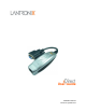
xDirect User Guide Part Number 900-653-R Revision A September 2012
Copyright & Trademark © 2012 Lantronix, Inc. All rights reserved. No part of the contents of this book may be transmitted or reproduced in any form or by any means without the written permission of Lantronix. Lantronix® is a registered trademark and xDirect™ and DeviceInstaller™ are trademarks of Lantronix, Inc. Windows® and Internet Explorer® are registered trademarks of Microsoft Corporation. Mozilla® and Firefox® are registered trademarks of the Mozilla Foundation. Chrome™ is a trademark of Google.
Table of Contents Copyright & Trademark ______________________________________________________ 2 Warranty _________________________________________________________________ 2 Contacts _________________________________________________________________ 2 Disclaimer ________________________________________________________________ 2 Revision History ___________________________________________________________ 2 List of Figures _____________________________________________________________ 8 List of Tables _________
Table of Contents 5: Configuration Using Web Manager 22 Accessing xDirect Using DeviceInstaller ________________________________________ 22 Network Configuration ______________________________________________________ 24 Network Mode ________________________________________________________ 24 Automatic IP Address Configuration ________________________________________ 24 Static IP Address Configuration ___________________________________________ 25 Ethernet Configuration ___________________________________
Table of Contents 7: Setup Mode: Server Configuration 39 Server Configuration (Option 0) ______________________________________________ 39 IP Address ______________________________________________________________ 39 Set Gateway IP Address ___________________________________________________ 40 Netmask: Number of Bits for Host Part _________________________________________ 40 Set DNS Server IP Address _________________________________________________ 40 Change Telnet Configuration Password ________________
Table of Contents 9: Setup Mode: Advanced Settings 55 Expert Settings (Option 5) ___________________________________________________ 55 TCP Keepalive Time In Seconds __________________________________________ 55 ARP Cache Timeout In Seconds __________________________________________ 55 CPU Performance _____________________________________________________ 55 Monitor Mode at Bootup _________________________________________________ 56 HTTP Port Number _____________________________________________________ 56
Table of Contents Appendix A: Troubleshooting and Contact Info 67 LEDs ___________________________________________________________________ 67 Status LED ___________________________________________________________ 67 Serial LEDs ___________________________________________________________ 68 RJ45 Ethernet LED _____________________________________________________ 68 Problems and Error Messages _______________________________________________68 Technical Support _______________________________________________
List of Figures Figure 2-1 Serial Tunneling Example ________________________________________________ 13 Figure 2-2 Direct TCP/IP or Redirector Configuration ____________________________________ 13 Figure 2-3 Product Label __________________________________________________________ 15 Figure 2-4 Sample Hardware Address ________________________________________________ 15 Figure 3-1 xDirect with PoE Connected to a Serial Device and Network ______________________ 16 Figure 3-2 Standard xDirect (without PoE) Conn
List of Tables Table 4-1 xDirect Configuration in DeviceInstaller _______________________________________ 19 Table 7-2 BootP/DHCP/AutoIP options _______________________________________________39 Table 7-3 Standard IP Network Netmasks _____________________________________________ 40 Table 8-2 Interface Mode Options ___________________________________________________ 43 Table 8-3 Common Interface Mode Settings ___________________________________________ 43 Table 8-4 Flow Control Options ______________________
1: Using this Guide Purpose and Audience This guide provides the information needed to configure, use, and update the xDirect device server. It is for system administrators and those responsible for installing and maintaining the xDirect. Chapter Summary The remaining chapters in this guide include: Chapter Description Chapter 2: Introduction Describes the main features of the xDirect and the protocols it supports.
1: Using this Guide Additional Documentation Visit the Lantronix Web site at www.lantronix.com/support/documentation for the latest documentation and the following additional documentation. Document xDirect Quick Start Description Provides the steps for getting the xDirect up and running. DeviceInstaller Online Help Provides instructions for using the Windows-based utility to configure the xDirect and other Lantronix device servers.
2: Introduction xDirect is a sleek and compact Serial-to-Ethernet device server, providing quick and easy Ethernet connectivity to virtually any device or machine with a serial interface. With an integrated Ethernet port and serial cable, multiple power options including PoE, and an industry-best five year warranty, xDirect provides a portable, extremely flexible, and highly affordable network connectivity solution in the market.
2: Introduction HVAC Systems Medical Devices Oil and Gas Exploration Security Alarms and Access Control Devices Telecommunications Equipment Time/Attendance Clocks and Terminals Universal Power Supply (UPS) Management Units Using a method called serial tunneling, the xDirect encapsulates serial data into packets and transports them over Ethernet. Using two xDirect units, connected by a network, virtual serial connections can extend across a facility or around the world.
2: Introduction Protocol Support The xDirect uses the Internet Protocol (IP) for network communications and the Transmission Control Protocol (TCP) to assure that no data is lost or duplicated and that everything sent to the connection arrives correctly at the target. Supported protocols include: ARP, UDP/IP, TCP/IP, BOOTP, ICMP, Telnet, TFTP, AutoIP, DHCP, HTTP, and SNMP for network communications. TCP/IP, UDP/IP, and Telnet for connections to the serial port as well as Telnet Com Port Control.
2: Introduction Product Information Label The product information label on the unit contains the following information about the specific unit: Part Number Revision Manufacturing Date Code Product Model Country of Origin Lantronix Datamatrix Barcode MAC Address (also used as Serial Number) Note: The hardware address on the label is also the product serial number. The hardware address on the label is the address for the Ethernet (eth0) interface.
3: Installation of xDirect This chapter describes how to install your xDirect and get it up and running in the shortest possible time. Package Contents Verify and inspect the contents of the xDirect package using the following list. If any item is missing or damaged, contact your place of purchase immediately. xDirect Power supply* Note: *Power supply available for non-Power Over Ethernet (PoE) units only.
3: Installation of xDirect 4. For non-PoE xDirect unit, supply power to your unit using the power supply that was included in the packaging. Note: The provided power supply is 5 VDC 1A. For all xDirect units power can also be supplied via pin 9 (+) and pin 5 (-) on the DB9F connector (voltage range = 5 VDC to 15 VDC). The xDirect will draw 1.3W max power.
4: Using DeviceInstaller This chapter covers the steps for getting the xDirect device server online and for viewing its current configuration. Note: DeviceInstaller is a free utility program provided by Lantronix that discovers, configures, upgrades, and manages Lantronix Device Servers. It can be downloaded from the Lantronix website at www.lantronix.com/support/downloads.
4: Using DeviceInstaller the Clear Status button to clear the window so you can ping the device again. Note: If you do not receive “Reply” messages, make sure the unit is attached to the network properly and the IP address assigned is valid for the particular network segment you are working with. If you are not sure, check with your systems administrator. 9. Click the Close button to close the dialog box and return to the main window.
4: Using DeviceInstaller Current Settings (continued) Description Comments Configurable field. Information about the xDirect. Double-click the field, type in the value, and press Enter to complete. This description or comment is not visible on other PCs or laptops using DeviceInstaller. Device Family Non-configurable field. Displays the xDirect’s device family as xDirect. Type Non-configurable field. Displays the device type as XDT232 or XDT485. ID Non-configurable field.
4: Using DeviceInstaller Current Settings (continued) Supports 485 Description Non-configurable field. xDirect supports the RS-485 protocol. Displays: False for XDT232. True for XDT485. Supports 921K Baud Rate Non-configurable field. Displays True. xDirect supports baud rates up to 921600 bits per second (bps). Supports HTTP Server Non-configurable field. Displays True. Supports HTTP Setup Non-configurable field. Displays True. Supports 230K Baud Rate Non-configurable field. Displays True.
5: Configuration Using Web Manager You must configure the unit so it can communicate on a network with your serial device. For example, you must set the way the unit will respond to serial and network traffic, how it will handle serial packets, and when to start or close a connection. The unit’s configuration is stored in nonvolatile memory and is retained without power. You can change the configuration at any time. The unit performs a reset after you change and store the configuration.
5: Configuration Using Web Manager Figure 5-2 Lantronix Web Manager 8. Navigate between pages by clicking links in the left pane of the Web Manager window.
5: Configuration Using Web Manager Network Configuration The unit’s network values display when you select Network from the main menu. The following sections describe the configurable parameters on the Network Settings page. Figure 5-3 Network Settings Network Mode 1. Click Network from the main menu. 2. Note the following: Network Mode For the xDirect, Wired Only is the only choice. It enables the Ethernet network connectivity.
5: Configuration Using Web Manager AutoIP Select Enable to permit the xDirect to generate an IP in the 169.254.x.x address range with a Class B subnet. Enable is the default. DHCP Host Name Enter the name of the host on the network providing the IP address. Note: Disabling BOOTP, DHCP, and AutoIP (all three checkboxes) is not advised as the only available IP assignment method will then be ARP or serial port. 4. When you are finished, click the OK button. 5. On the main menu, click Apply Settings.
5: Configuration Using Web Manager Server Configuration The unit’s server values display when you select Server from the main menu. The following sections describe the configurable parameters on the Server Settings page. Figure 5-4 Server Settings To configure the xDirect device server settings: 1. On the main menu, click Server. 2.
5: Configuration Using Web Manager TCP Keepalive (secs) TCP Keepalive time defines how many seconds the unit waits during an inactive connection before checking its status. If the unit does not receive a response, it drops that connection. Enter a value between 0 and 60 seconds. 0 disables keepalive. The default setting is 45. Monitor Mode @ Bootup Select Disable to disable entry into the monitor mode using the yyy or xx1 key sequence at startup.
5: Configuration Using Web Manager Host List Configuration The xDirect scrolls through the host list until it connects to a device listed in the host list table. After a successful connection, the unit stops trying to connect to any others. If this connection fails, the unit continues to scroll through the table until the next successful connection. The host list supports a minimum of 1 and a maximum of 12 entries. Each entry contains an IP address and a port number.
5: Configuration Using Web Manager Channel 1 Configuration The Channel 1 configuration defines how the serial ports respond to network and serial communication. Serial Settings To configure the channel’s serial settings: 1. On the main menu, click Serial Settings (under Channel 1) to display the Serial Settings window. Figure 5-6 Channel Serial Settings 2.
5: Configuration Using Web Manager Baud Rate The unit and attached serial device, such as a modem, must agree on a speed or baud rate to use for the serial connection. Valid baud rates are 300, 600, 1200, 2400, 4800, 9600, 19200, 38400, 57600, 115200, and 230400 baud. Additionally, 921600 and 460800 baud rates are available when CPU is set to High. The default setting is 9600. Data Bits Indicates the number of bits in a transmitted data package. The default setting is 8.
5: Configuration Using Web Manager At Time of Disconnect Select Yes to clear the output buffer when the network connection to or from the device is disconnected. The default setting is No. 3. When you are finished, click the OK button. 4. On the main menu, click Apply Settings. Connection Settings - TCP To configure a channel’s TCP settings: 1. On the main menu, click Connection. The Connection Settings window for the channel displays. Figure 5-7 TCP Connection Settings 2.
5: Configuration Using Web Manager Password Required Determines whether a password is required for an incoming passive connection. This field is not available when a password is set for Telnet mode. The default setting is No. Password If Password Required was set to Yes, enter the password for passive connections. Modem Escape Sequence Pass Through Disable or enable the xDirect’s ability to send the escape sequence. The default is Yes (send the escape sequence).
5: Configuration Using Web Manager Connect Response A single character is transmitted to the serial port when there is a change in connection state. The default setting is None. Use Hostlist If this option is set to Yes, the device server scrolls through the host list until it connects to a device listed in the host list table. Once it connects, the unit stops trying to connect to any others.
5: Configuration Using Web Manager Figure 5-8 UDP Connection Settings Connect Protocol Protocol Select UDP from the drop-down menu. Datagram Mode Datagram Type Configures the remote IP or network broadcast address and the remote port. Enter 01 for directed or broadcast UDP. The default setting is 00. Accept Incoming Select Yes to accept incoming UDP datagrams. The default setting is Yes. Endpoint Configuration Local Port Enter the local port number.
5: Configuration Using Web Manager Apply Settings 1. To save and apply the configuration changes to the device server, click the Apply Settings button. Note: Clicking OK on each page does not change the configuration on the device. Clicking the OK button tells the xDirect what changes to use; the Apply Settings button makes the changes permanent and reboots the xDirect. Apply Defaults 1. Click the Apply Defaults button to set the device server back to the default settings.
6: Configuration Via Telnet or Serial Port (Setup Mode) You must configure the unit so it can communicate on a network with your serial device. As an alternative to using a web browser, as described in the previous chapter, you can use the following procedures remotely or locally: Use a Telnet connection to configure the unit over the network. Use a terminal or terminal emulation program to access the serial port locally.
6: Configuration Via Telnet or Serial Port (Setup Mode) Password :---Press Enter for Setup Mode 3. Enter User Name (user name is admin and cannot be changed). Pressing the Enter key after entry is not necessary. The Password field will appear. 4. Enter Password (default password is PASS). Pressing the Enter key after entry is not necessary. You will be prompted to enter Setup Mode. Note: Password can be modified or disabled. See Server Configuration (on page 26). 5.
6: Configuration Via Telnet or Serial Port (Setup Mode) TCP Re-transmission timeout: 500 ms Alternate MAC: disabled Ethernet connection type: auto-negotiate Change Setup: 0 Server 1 Channel 1 5 Expert 6 Security 7 Defaults 8 Exit without save 9 Save and exit Your choice? _ 6. Select an option on the menu by entering the number of the option in the Your choice? field and pressing Enter. 7. To enter a value for a parameter, type the value and press Enter, or to confirm a current value, just press Enter. 8.
7: Setup Mode: Server Configuration This chapter explains how to configure the network settings. Note: Current values display in parentheses. Server Configuration (Option 0) The unit’s basic network parameters display when you select Server configuration (option 0). The IP Address, Set Gateway IP Address, and Netmask fields display the current values. Figure 7-1 Network Settings IP Address : (000) .(000) .(000) .
7: Setup Mode: Server Configuration Set Gateway IP Address The gateway address, or router, allows communication to other LAN segments. The gateway address should be the IP address of the router connected to the same LAN segment as the unit. The gateway address must be within the local network. The default setting is N (No), meaning the gateway address has not been set. To set the gateway address, type Y and enter the address.
7: Setup Mode: Server Configuration Change Telnet Configuration Password Setting the Telnet configuration password prevents unauthorized access to the setup menu through a Telnet connection to port 9999 or through web pages. The password must have 4 characters. The default setting is N (No).
8: Setup Mode: Channel Configuration This chapter explains how to configure the serial port. Notes: Current values display in parenthesis. You must enter some values in hexadecimal notation. See Appendix E: Binary to Hexadecimal Conversions. Channel 1 (Option 1) Select Channel 1 (Option 1) from the Change Setup menu to define how the serial port responds to network and serial communications. The following sections describe the configurable parameters within the Channel configuration menu.
8: Setup Mode: Channel Configuration I/F (Interface) Mode The Interface (I/F) Mode is a bit-coded byte entered in hexadecimal notation. The default setting is 4C. I/F Mode (4C) ? _ The following table displays available I/F Mode options: Note: All bit positions in the table that are blank represent “don’t care” bits for that particular option, which can be set to either a 0 or 1 value.
8: Setup Mode: Channel Configuration Use the following table to select flow control options: Table 8-4 Flow Control Options Flow Control Option Hex No flow control 00 XON/XOFF flow control 01 Hardware handshake with RTS/CTS lines 02 XON/XOFF pass characters to host 05 Port Number The setting represents the source port number in TCP connections. It is the number that identifies the channel for remote initiating connections. Port No (10001) ? _ The default setting for Port 1 is 10001.
8: Setup Mode: Channel Configuration Note: All bit positions in the table that are blank represent “don’t care” bits for that particular option, which can be set to either a 0 or 1 value.
8: Setup Mode: Channel Configuration b) Response A single character is transmitted to the serial port when there is a change in connection state: C = connected, D = disconnected, N = host unreachable. The IP address of the host connecting to the CoBos device will be provided when you use verbose mode. Character Response This option is overridden when the Active Start Modem Mode or Active Start Host List is in effect. Default setting is Nothing (quiet).
8: Setup Mode: Channel Configuration Command String Result if remote IP is 129.1.2.3 and remote port is 1234 C0.0.0.0/0 Enters Monitor Mode. Cwww.lantronix.com/80 Tries to connect to the Lantronix web server if the (www.lantronix.com) is configured in the DNS server database. Host List Option (Hostlist) Autostart (Automatic Connection) If you enable Autostart, the unit automatically connects to the remote IP address and remote port specified when the firmware starts.
8: Setup Mode: Channel Configuration SendChar 1 SendChar 2 (00) (00) To enable the hostlist: 1. Enter a Connect Mode of 0x20 (2X), where X is any digit. The menu shows you a list of current entries already defined in the product. 2. To delete, modify, or add an entry, select Yes. If you enter an IP address of 0.0.0.0, that entry and all others after it are deleted. 3. After completing the hostlist, repeat the previous step if necessary to edit the hostlist again. 4.
8: Setup Mode: Channel Configuration Data Echo & Modem Response Full Verbose: The unit echoes modem commands and responds to a command with a message string shown in the table below. Numeric Response: The unit echoes modem commands and responds to a command with a numeric response. Full Verbose: The unit does not echo modem commands and responds to a command with a message string shown in the table below.
8: Setup Mode: Channel Configuration The character string ATH is received, terminated with a carriage return. The unit responds affirmatively according to the selected echo/response mode and drops the network connection. The serial interface reverts to accepting command strings. If this sequence is not followed, the unit remains in data transfer mode. Table 8-10 Modem Mode Commands Modem Mode Command Function ATDTx.x.x.x,pppp or ATDTx.x.x.x/pppp or ATDTx.x.x.
8: Setup Mode: Channel Configuration Disable or enable the xDirect's ability to show the IP address after RING in Modem Mode. The default is Y (Yes), to show the IP address. Auto Increment Source Port Auto increment source port (N) ? _ Y (Yes) auto increment the source port. The xDirect increments the port number used with each new connection. Remote IP Address This is the destination IP address used with an outgoing connection.
8: Setup Mode: Channel Configuration Table 8-11 Disconnect Mode Options Disconnect Mode Option 7 Disconnect when Modem Control In is not asserted (6) Telnet Com Port Cntrl and terminal type Hard disconnect 5 4 3 2 1 0 1 0 Ignore Modem Control In Channel (port) password 6 setup(1) 1 (2) 1 (3) 0 1 Disable hard disconnect State LED off with connection Disconnect with EOT (^D) (4) 1 (5) 1 (1) The Telnet Com Port Control feature is used in conjunction with Com Port Redirector.
8: Setup Mode: Channel Configuration Pack Control The packing algorithms define how and when packets are sent to the network. The standard algorithm is optimized for applications in which the unit is used in a local environment, allowing for very small delays for single characters, while keeping the packet count low. The alternate packing algorithm minimizes the packet count on the network and is especially useful in applications in a routed Wide Area Network (WAN).
8: Setup Mode: Channel Configuration unit sends immediately after recognizing the transmit condition (sendchar or timeout). The default setting is 0. Note: A transmission might occur if status information needs to be exchanged or an acknowledgment needs to be sent. DisConnTime (Inactivity Timeout) Use this parameter to set an inactivity timeout. The unit drops the TCP connection to the local port if there is no activity on the serial line before the set time expires.
9: Setup Mode: Advanced Settings Expert Settings (Option 5) Note: You can change these settings using telnet or serial connections only, not on the Web Manager. Caution: Changing the expert settings can drastically affect the performance and access to the product. These settings should only be changed by an experienced network administrator. Select 5 to configure expert settings.
9: Setup Mode: Advanced Settings Increasing CPU clock speed consumes more power and generates more heat. This reduces the maximum operating temperature specification. See the appropriate product brief for details. Monitor Mode at Bootup This option allows you to disable all entries into Monitor Mode during startup, except for the ‘xxx’ sequence. This prevents entry using yyy, zzz, xx1, and yy1 key sequences (only during the bootup sequence). The default for disabling Monitor Mode at bootup is N (No).
9: Setup Mode: Advanced Settings Caution: Disabling both Telnet Setup and Port 77FE will prevent users from accessing the setup menu from the network. Disabling Port 77FE also disables the Web from configuring the device. Select 6 to configure security settings.
9: Setup Mode: Advanced Settings Disable TFTP Firmware Update This setting defaults to the N (No) option. The Y (Yes) option disables the use of TFTP to perform network firmware upgrades. With this option, you can download firmware upgrades over the serial port using DeviceInstaller’s Recover Firmware procedure. See Chapter 10: Firmware Upgrades.
9: Setup Mode: Advanced Settings Change Keys (N) Y Enter Keys: **-**-**-**-**-**-**-**-**-**-**-**-**-**-**-** 1. When prompted to enable encryption, select Y. 2. When prompted, enter the encryption key length. The xDirect supports 128-, 192-, and 256-bit encryption key lengths. 3. When prompted to change keys, select Y. 4. At the Enter Keys prompt, enter your encryption key. The encryption keys are entered in hexadecimal.
9: Setup Mode: Advanced Settings Channel 1 Configuration Defaults Baudrate 9600 I/F Mode 4C (1 stop bit, no parity, 8 bit, RS-232C) Flow 00 TCP port number 10001 Connect Mode C0 (always accept incoming connection; no active connection startup) Send ‘+++’ in Modem Modem Enabled Show IP addr after ‘RING’ Enabled Auto increment source port Disabled Hostlist retry counter 3 Hostlist retry timeout 250 (msec) Start Character 0x0D (CR) All other parameters 0 Expert Settings Defaults TCP Keep
10: Firmware Upgrades Obtaining Firmware You can obtain the most up-to-date firmware and release notes for the unit from the Lantronix web site (www.lantronix.com/support/downloads) or by using anonymous FTP (ftp.lantronix.com/pub). Reloading Firmware There are several ways to update the unit's internal operational code (*.ROM): using DeviceInstaller (the preferred way), using TFTP, or using the serial port. You can also update the unit's internal Web interface (*.COB) using TFTP or DeviceInstaller.
10: Firmware Upgrades Figure 10-2 TFTP Window After the firmware has been loaded and stored, which takes approximately 8 seconds to complete, the unit performs a power reset. Using TFTP: Command Line Interface To download new firmware from a computer: 1. Enter the following from a TFTP command line interface: tftp –i put The following examples demonstrate the TFTP command sequence to download the .rom file and the .cob file: tftp –i 192.168.1.
10: Firmware Upgrades 6. Click OK to download the file. 7. When prompted, reset the device. Status messages and a progress bar at the bottom of the screen show the progress of the file transfer. When the file transfer completes, the message “Successful, Click OK to Close” displays. 8. Click the OK button to complete this procedure. Note: Help.
11: Monitor Mode Monitor Mode is a command-line interface used for diagnostic purposes. There are two ways to enter Monitor Mode: locally using the serial port or remotely using the network. Entering Monitor Mode Using the Serial Port To enter Monitor Mode locally: 1. Follow the same steps used for setting the serial configuration parameters. 2. Instead of typing three x keys, however: Type zzz (or xx1) to enter Monitor Mode with network connections.
11: Monitor Mode Monitor Mode Commands The following commands are available in Monitor Mode. Many commands have an IP address as an optional parameter (xxx.xxx.xxx.xxx). If you enter the IP address, the command is applied to another unit with that IP address. If you do not enter the IP address, the command is executed locally. Note: All commands must be in capital letters. Responses to some of the commands are in Intel Hex format. Table 11-2 Monitor Mode Commands Command Command Name Function VS x.x.x.
11: Monitor Mode Command Command Name Function (continued) Set IP address, host bits, gateway, and DNS server IP co Example: co 192.168.0.10 8 192.168.0.1 10001 192.168.1.10 with 192.168.0.10 = IP address of the xDirect 8 = number of host bits 192.168.0.1 = gateway IP address 10001 = port number of the xDirect 192.168.1.10 = IP address of the DNS Server The xDirect stores the setup and performs a reset. It sends an X before the reset if the command was OK.
Appendix A: Troubleshooting and Contact Info This chapter discusses how you can diagnose and fix errors quickly without having to contact a dealer or Lantronix. It helps to connect a terminal to the serial port while diagnosing an error to view summary messages that may display. When troubleshooting, always ensure that the physical connections (power cable, network cable, and serial cable) are secure. Note: Some unexplained errors might be caused by duplicate IP addresses on the network.
Appendix A: Troubleshooting and Contact Info Serial LEDs Two serial LEDs on top of the xDirect unit, directly adjacent to the “X” Power/Status LED, indicate transmit and receive data activity: Table A-3 Serial LEDs Serial LED Color Condition TX Serial LED Green Indicates transmit data activity. RX Serial LED Amber Indicates receive data activity. RJ45 Ethernet LED The following two tables describe the meaning of the left and right LED colors on the Ethernet.
Appendix A: Troubleshooting and Contact Info Problem/Message (continued) Reason When you Telnet to port 9999, the "Press Enter to go into Setup Mode" message displays. However, nothing happens when you press Enter, or your connection is closed. You did not press Enter quickly Telnet to port 9999 again, but press Enter enough. You only have 5 as soon as you see the "Press Enter to go seconds to press Enter before into Setup Mode" message. the connection is closed.
Appendix A: Troubleshooting and Contact Info Problem/Message (continued) Reason When you try to enter the setup mode The issue is most likely on the device server using the serial something covered in the port, you get no response. previous problem, or possibly, you have Caps Lock on. Solution Double-check everything in the problem above. Confirm that Caps Lock is not on. Reference Serial Settings (on page 29) or http://ltxfaq.custhelp.com/app/answers/list.
Appendix A: Troubleshooting and Contact Info Technical Support United States Phone: (800) 422-7044 Please check our online knowledge base or send a question to Technical Support at http:// www.lantronix.com/support. Europe, Middle East and Africa Phone: (33) 13-930-4172 Email: eu_techsupp@lantronix.com or eu_support@lantronix.com Firmware downloads, FAQs, and the most up-to-date documentation are available at http:// www.lantronix.
Appendix B: Connections and Pinouts The xDirect has a DB9F DCE connector, and an Ethernet 10/100 RJ45 interface. The xDirect can be powered via a mini USB-B jack with a provided 5 VDC power supply, or Ethernet PoE (hardware optional), or DB9F pin 9 and 5.
Appendix B: Connections and Pinouts Figure B-4 DB9F in RS485 (2-Wire) Mode (xDirect485 & PoE Models) Ethernet Connector Pinouts The xDirect supports 10/100 Mbps half or full duplex Ethernet through an RJ45 connector. For PoE option, the xDirect is compliant as an IEEE 802.3af Power Device, Class . Power connections can be established via data pins (1 & 2 and 3 & 6), or spare pins (4 & 5 and 7 & 8).
Appendix B: Connections and Pinouts Power Jack (Mini USB-B) The 5 VDC power supply included with standard xDirect devices (and not included the xDirect PoE model) connects to standard xDirect units through a mini USB connector on the side of the device.
Appendix C: Technical Specifications Table C-1 xDirect Technical Specifications Category Description CONTROLLER CPU Lantronix DSTni-EX enhanced 16-bit x86 architecture, 48 MHz clock MEMORY Internal CPU Memory 256 KB zero wait state SRAM Flash 8 Mbits (1 MB) POWER INPUT1,2 1 Mini USB-B jack Accepts 5 VDC Wall Adapter (included in non-PoE models) Pin 1 (+) and pin 4, 5 (-) Data pins = no connection Note: User can also use USB powering from a PC as long as the USB source is able to provide 5V
Appendix C: Technical Specifications Category (continued) Description NETWORK INTERFACE 1 RJ45 Connector Ethernet LEDs Magnetic Isolation WEIGHT 10Base-T/100Base-TX Ethernet port Software selectable Ethernet speed 10/100/Auto Software selectable Half/Full/Auto duplex 15 KV ESD protection by TVS diodes 10/100 Mbit Link (green/amber) 10/100 Activity (green/amber) 1500 VAC between Ethernet connection and internal logic 0.068 kg (0.
Appendix D: Alternative Ways to Assign an IP Address Earlier chapters describe how to assign a static IP address using DeviceInstaller, Web Manager, and Setup Mode (through a Telnet or serial connection). This section covers other methods for assigning an IP address over the network. DHCP The unit ships with a default IP address of 0.0.0.0, which automatically enables DHCP.
Appendix D: Alternative Ways to Assign an IP Address BOOTP Similar to DHCP, but for smaller networks. Automatically assigns the IP address for a specific duration of time. ARP and Telnet If the unit has no IP address, you can use Address Resolution Protocol (ARP) method from UNIX and Windows-based systems to assign a temporary IP address. To assign a temporary IP address: 1.
Appendix E: Binary to Hexadecimal Conversions Many of the unit's configuration procedures require you to assemble a series of options (represented as bits) into a complete command (represented as a byte). The resulting binary value must be converted to a hexadecimal representation. Use this chapter to learn to convert binary values to hexadecimals or to look up hexadecimal values in the tables of configuration options.
Appendix E: Binary to Hexadecimal Conversions Figure E-2 Windows Scientific Calculator 4. Click Hex. The hexadecimal value appears.
Appendix F: Compliance Manufacturer’s Name & Address Lantronix, Inc. 167 Technology Drive, Irvine, CA 92618 USA Tel: 800-526-8766 Tel: 949-453-3990 Fax: 949-450-7249 Declares that the following product: Product Name Model: xDirect Device Server Conforms to the following standards or other normative documents: Safety UL 60950-1, 2nd Edition CAN/CSA-C22.2 No.
Appendix F: Compliance RoHS Notice All Lantronix products in the following families are China RoHS-compliant and free of the following hazardous substances and elements: Lead (Pb) Cadmium (Cd) Product Family Name Mercury (Hg) Hexavalent Chromium (Cr (VI)) Polybrominated biphenyls (PBB) Polybrominated diphenyl ethers (PBDE) Toxic or hazardous Substances and Elements Lead (Pb) Mercury (Hg) Cadmium (Cd) Hexavalent Chromium (Cr (VI)) Polybrominate d biphenyls (PBB) Polybrominated diphenyl e