MPS/LPS Installation Guide For the MPS100, LPS1-T and LPS1-2 Micro Print Servers
The information in this guide may change without notice. The manufacturer assumes no responsibility for any errors which may appear in this guide. AppleTalk, Chooser, and Macintosh are trademarks of Apple Computer Corporation. LaserJet and Bitronics are trademarks of Hewlett Packard. Centronics is a registered trademark of Centronics Data Computer Corporation. PostScript is a trademark of Adobe Systems, Inc. DEC and LAT are trademarks of Digital Equipment Corporation.
Contents 1: Introduction.......................................................................... 1-1 1.1 How to Use This Manual................................................................. 1-1 2: Installation............................................................................ 2-1 2.1 MPS/LPS Product Description ........................................................ 2-1 2.2 Installing the MPS ........................................................................... 2-2 3: Getting Started.
Contents 5.5 NetWare Host Troubleshooting....................................................... 5-4 6: LAT Configuration ............................................................... 6-1 6.1 Printing Directly to a Port................................................................ 6-1 6.2 LAT Host Troubleshooting.............................................................. 6-2 7: AppleTalk Configuration ..................................................... 7-1 7.1 Bitronics..........................
Contents E: Specifications ......................................................................E-1 E.1 Power Information .......................................................................... E-1 E.2 Environmental Limitations.............................................................. E-1 F: Frequently-used Commands ..............................................F-1 F.1 Conventions..................................................................................... F-1 F.2 Server Commands .........
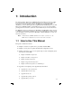
1: Introduction The Lantronix Micro Print Servers (MPS100, LPS1-T and LPS1-2 models) are multiprotocol print servers that provide shared network access to printers for a variety of network protocols and operating systems. The MPS supports the TCP/IP, IPX (NetWare), Local Area Transport (LAT), AppleTalk, and LAN Manager protocols. The LPS supports TCP/IP, NetWare, and LAT. Both types of servers can queue multiple pending jobs and service those jobs in the order in which they are received from hosts.
How to Use This Manual ❍ Introduction Appendix F, Frequently-used Commands Read chapters 2 through 4 in order, then proceed to the protocol-specific chapter that relates to your network. Refer to Appendix F as needed. The Print Server Reference Manual, located on the CD-ROM and web site, provides additional information about configuring and using your MPS.
2: Installation This chapter describes the various MPS models and shows how to install them into a basic network situation. 2.1 MPS/LPS Product Description The front panel of the MPS100 has a Test button, 3 LEDs, a power connector, and an RJ45 connector for 100BASE-T. The rear panel has a Centronics connector.
Installing the MPS Installation 2.2 Installing the MPS The following diagram shows a properly-installed MPS: PARALLEL PRINTER 3 Network Connection 1 2 To install the MPS, complete the following steps in order. Refer to the numbers in the figure for help. 1 Connect the MPS Centronics connector directly to your printer’s connector. 2 Connect an Ethernet cable to your MPS’s RJ45 or BNC connector. 3 Attach one end of the power cable to the MPS; plug the other end into an electrical outlet.
Installation Installing the MPS 5 Allow 45 seconds for the unit to fully boot. The LINK LED will be lit if there is a valid network connection. The ACT LED gives information about what the MPS is doing; for example, when code is being downloaded as the unit boots, the LED will blink green quickly. If you have connected a 100BASE-T cable (MPS100 only), The Link and 100MBit LEDs should both be solid green. If not, check your network connection. 6 Print a Test page by pressing the Test/Reset button.
3: Getting Started It is important to consider the following points before logging into and configuring the MPS: ◆ You must configure the MPS IP address before any TCP/IP functionality is available. (See Setting the IP Address on page 4-1) You cannot use the ThinWeb Manager until you have configured an IP address. ◆ Changing any server, service, or port setting requires privileged user status. The default privileged password is system. ◆ The login password is required for remote console logins.
Services Getting Started Incoming Telnet is only possible if your MPS has an IP address configured. Incoming Telnet is enabled by default to allow TCP/IP connections. To change this setting, use the Define Server Incoming command described in the Command Reference chapter of the Print Server Reference Manual located on the CD-ROM. Incoming logins do not prompt for a login password, so you may wish to disable them for security reasons.
4: TCP/IP Configuration The EZWebCon configuration software is the easiest way to configure the MPS. The following sections cover IP address configuration and print configuration methods for TCP/ IP hosts. 4.1 Setting the IP Address The MPS IP address must be configured before any TCP/IP functionality is available. Use one of the following methods to set the IP address: EZWebCon; a directed Ping packet; a BOOTP, DHCP, or RARP reply; or commands entered via the command line interface. 4.1.
Setting the IP Address TCP/IP Configuration On a UNIX host, create an entry in the host’s ARP table and substitute the intended IP address and the hardware address of the MPS, then ping the MPS. This process typically requires superuser privileges. Figure 4-1: ARP and Ping on UNIX # arp -s 192.0.1.228 00-80-a3-xx-xx-xx % ping 192.0.1.228 In order for the ARP command to work on Windows, the ARP table on the PC must have at least one IP address defined other than its own.
TCP/IP Configuration LPR Printing 4.1.3 Using a BOOTP, DHCP, or RARP Reply At boot time a host-based DHCP, BOOTP, or RARP server can respond to an MPS request for an available IP address. For information about configuring the DHCP, BOOTP, or RARP server, see your host documentation. 4.1.4 Using the Command Line Interface 1 Connect to the serial port (Port_1) using a console terminal or a terminal emulation program, and press Return. The serial port settings are 9600 baud, 8 bits, 1 stop bit, no parity.
LPR Printing TCP/IP Configuration ◆ The MPS cannot print multiple copies of the print job when using the “-#n” lpr option. ◆ If two print queues on the host refer to two services on the same MPS, they must use separate spooling directories. ◆ No special purpose input or output filters can be used when printing via LPR. If this functionality is necessary, use the named pipe interface program in the RTEL print queue configuration software. 4.2.1 LPR on Windows NT 3.5.
TCP/IP Configuration 4 Select the Add Port button and click Next. 5 Select LPR Port. Note: 6 LPR Printing If LPR Port is not an option, open the Network Control Panel and add “Microsoft TCP/IP Printing” to the List of services. Enter the name or IP address of your MPS on the first line, and enter the name of your MPS print service on the second line.
LPR Printing TCP/IP Configuration 7 Select the manufacturer and printer type. 8 Enter the queue name. 9 If applicable, choose Shared and select the type of operating system that the printer will be working with. (First confirm that the print queue is working.
TCP/IP Configuration LPR Printing 10 Test the printer by choosing Yes and clicking Finish. 4.2.2 LPR on Windows 95/98 To enable LPR printing on Windows 95/98, you must download and install the LPR for Windows 95/98 application from the Lantronix CD included with the product. 1 From the Distribution CD, install Lantronix LPR. 2 Follow the directions in the readme file to configure LPR on your PC. 4.2.
LPR Printing TCP/IP Configuration This will create a host queue named mps_prt. The rm parameter is the name of the MPS in the host’s address file, the rp parameter is the name of the service as it exists on the MPS, and the sd parameter specifies the name of a directory used to hold temporary spooling files. 3 Create a world-writable spooling directory using the mkdir command.
TCP/IP Configuration LPR Printing 5 From the next dialog box, choose Remote Printing. 6 The Add a Standard Remote Print Queue dialog box will appear. Enter the following information. 7 ❍ The name of the print queue, ❍ The name of the MPS unit, ❍ The name of the MPS service, ❍ The type of print spooler on the remote server, and ❍ A description of the printer on the remote server. A dialog box will appear: “Added print queue mps_prt”. Click Done.
LPR Printing TCP/IP Configuration ❍ The remote cancel model, and ❍ The remote status model. 4.2.6 LPR on SCO UNIX Hosts LPR is supported in SCO V3.2 release 4 with TCP/IP Version 1.2 and greater. To configure a print queue using LPR, issue the mkdev rlp command. This will install the Berkeley remote printing files and executable programs. Note: The mkdev rlp command should only be issued once, or serious problems will occur. If this happens, contact SCO technical support.
TCP/IP Configuration LPR Printing During initial configuration, the queue name must be the same as the remote printer name. However, you may change the queue name later by manually editing the printcap file. 4.2.7 RTEL Functionality If the LPR method of printing is not adequate for an application (for example, if you need banners before jobs, or more flexibility), configure the Lantronix-supplied RTEL software on the host.
Unix Host Troubleshooting TCP/IP Configuration 4.3 Unix Host Troubleshooting Table 4-1: TCP Troubleshooting Area to Check Explanation The MPS IP address and name are entered in the host file Telnet to the MPS using the name in the host file and verify that the MPS name is resolvable and that the MPS is reachable via the network.
5: NetWare Configuration The EZWebCon configuration software is the easiest way to configure the MPS. The following sections cover print configuration methods for NetWare hosts. Note: The MPS needs an IP address before you can use EZWebCon. See Setting the IP Address on page 4-1 for instructions. This chapter explains creating NDS print queues with NetWare Administrator and with the PCONSOLE Quick Setup option. To create NDS print queues, you must be running NetWare version 4.x with NDS capabilities.
NetWare Administrator Quick Setup Print Queues NetWare Configuration 5.2.2 Configure your MPS 1 License NDS on your MPS using the string obtained from Lantronix. Figure 5-1: Licensing NDS Local>> DEFINE PROTOCOL NETWARE DSLICENSE licensestring 2 Define the directory service tree in which the MPS is located.
NetWare Configuration PCONSOLE Print Queues To create a print queue with the Quick Setup option: 1 Start the NetWare Administrator. 2 In the Directory Tree windows, select the context in which to install the printer. 3 From the Menu Bar, select Tools: Print Services Quick Setup. 4 In the Print Server Name field, enter the name of your MPS (viewable by entering the Show Server command at the Local> prompt).
NetWare Host Troubleshooting NetWare Configuration 5.5 NetWare Host Troubleshooting Table 5-1: NetWare Host Troubleshooting (Bindery Mode) Area to Check Explanation The print server names in PCONSOLE match the MPS name and its service name Use PCONSOLE to check. The MPS NetWare access table Use the Show Protocols NetWare Access command. Scanning too many file servers can cause a delay between jobs. Configure the access list to only scan for jobs on the file servers of interest.
NetWare Configuration NetWare Host Troubleshooting Table 5-3: NDS Errors from the File Server Code Meaning Remedy 0xfffffda7 Object could not be found in the given context Check the MPS server name, DScontext, and DStree to ensure the printer server is set up correctly with PCONSOLE. 0xfffffda5 Requested attribute could not be found Use PCONSOLE to ensure that the MPS has associated printers and the printers have associated queues.
6: LAT Configuration The EZWebCon configuration software is the easiest way to configure the MPS. The following sections cover print configuration methods for LAT hosts. Note: The MPS needs an IP address before you can use EZWebCon. See Setting the IP Address on page 4-1 for instructions. LAT print queues can be created by printing to a port or printing to a service. Printing directly to a port requires no MPS configuration. Note: Printing directly to a port is the easiest method for printing to the MPS.
LAT Host Troubleshooting LAT Configuration 6.2 LAT Host Troubleshooting By default, the LAT error message codes on the host are not translated into text error messages. If a LAT job fails and appears in the queue with an eight-digit hex result code, the code can be translated by issuing the following commands: Figure 6-4: Translating LAT Error Codes $ SHOW QUEUE/FULL/ALL queue_name (note the error code nnnnnnnn) $ SET MESSAGE SYS$MESSAGE:NETWRKMSG.
7: AppleTalk Configuration The EZWebCon configuration software is the easiest way to configure the MPS. The following sections cover print configuration methods for AppleTalk hosts. Note: The MPS needs an IP address before you can use EZWebCon. See Setting the IP Address on page 4-1 for instructions. Note: Macintoshes that do not support EtherTalk will need either an Ethernet card or a LocalTalk-to-EtherTalk router to use the MPS. Note: The LPS1-T and LPS1-2 do not support AppleTalk Protocol. 7.
AppleTalk Host Troubleshooting Note: AppleTalk Configuration If no router is present on the network, the MPS will not accept AppleTalk print jobs for 60 seconds after booting. 7.4 AppleTalk Host Troubleshooting Table 7-1: AppleTalk Host Troubleshooting Area to Check Explanation The printer is available to be selected in the Chooser Make sure the printer is in the right zone. Bidirectional communication Lock the printer in PostScript mode and issue the Test Service PostScript Count n command.
8: DLC Configuration for LAN Manager The EZWebCon configuration software is the easiest way to configure the MPS. This chapter explains DLC/Digital Network Port configuration for Windows NT 4.x hosts. Note: The Server needs an IP address before you can use EZWebCon. See Setting the IP Address on page 4-1 for instructions. Printing using an LPD client is the preferred method for sending print jobs to the MPS. Windows 95 does not support DLC printing (see Chapter 4 for more information). 8.
DLC Configuration 7 Select Job-based. 8 Select the manufacturer and printer type. 9 Enter the queue name. DLC Configuration for LAN Manager 10 If applicable, choose Shared and select the operating system the printer will be working with. (First confirm that the print queue is working.) 11 Test the printer.
A: Contact Information If you are experiencing an error that is not listed in Appendix B: or if you are unable to fix the error, contact your dealer or Lantronix Technical Support at 800-422-7044 (US) or 949453-3990. Technical Support is also available via Internet email at support@lantronix.com. A.
B: Troubleshooting This Appendix discusses how to diagnose and fix errors quickly yourself without having to contact a dealer or Lantronix. It will help to connect a terminal to the serial port while diagnosing an error to view any summary messages that are displayed. When troubleshooting, always ensure that the physical connections (power cable, network cable, and serial cable) are secure.
Power-up Troubleshooting Troubleshooting Problem situations and error messages are listed in Table B-2. If you cannot find an explanation for your problem, try to match it to one of the other errors. If you cannot remedy the problem, contact your dealer or Lantronix Technical Support. Table B-2: Power-up Problems and Error Messages Problem/Message Error Remedy The MPS is The unit or its power supply is connected to a power damaged. source, but there is no LED activity.
Troubleshooting DHCP Troubleshooting Table B-2: Power-up Problems and Error Messages, cont. Problem/Message Error Remedy The terminal shows a The MPS is not connected Boot> prompt rather properly to the Ethernet. than a Local> prompt. The MPS Ethernet address is invalid. Ensure that the MPS is firmly connected to a functional and properly-terminated network node. The MPS passes power-up diagnostics, but attempts to download new Flash ROM code from a network host.
BOOTP Troubleshooting Troubleshooting B.3 BOOTP Troubleshooting If the BOOTP request is failing and you have configured your host to respond to the request, check these areas: Table B-4: BOOTP Troubleshooting Area to Check Explanation BOOTP is in your system’s /etc/services file BOOTP must be an uncommented line in /etc/services. The MPS is in the loadhost’s /etc/hosts file The MPS must be in this file for the host to answer a BOOTP or TFTP request.
Troubleshooting Printing Problems B.5 Printing Problems Table B-6: General Printing Problems Area to Check Explanation Physical connections To test a non-PostScript printer, use the Test Port MPS Count 100 command. This command will send 100 lines of test data out the parallel port so you can see if the printer is receiving data.
Entering Commands at the Boot Prompt Troubleshooting Table B-7: PostScript Troubleshooting, cont. Area to Check Explanation Service Characteristics Issue the Show Service Characteristics command. If the service rating is zero, the parallel port is in use. Verify that the PostScript characteristic and appropriate protocols have been enabled on the service. Port Counters If PostScript jobs appear to print but nothing comes out of the printer, verify the amount of data sent from the host.
Troubleshooting Entering Commands at the Boot Prompt A series of commands called Boot Configuration Program (BCP) commands can be entered at the Boot> prompt to configure the MPS. These commands are a subset of the entire MPS command set. For example, a typical TCP/IP configuration might use the following commands: Figure B-1: BCP Command Examples Boot> Set IPADDRESS 192.0.1.229 Boot> Set SOFTWARE /tftpboot/MPS.SYS Boot> Set LOADHOST 192.0.1.188 Boot> Set SECONDARY 192.0.1.
Entering Commands at the Boot Prompt Set Hardware xx-xx-xx Troubleshooting Specifies the last three numbers of the server’s Ethernet address. The first three numbers will be supplied automatically. The Ethernet address should have been set at the factory. Setting an incorrect address could cause serious network problems. Set IPAddress ip_address Specifies this server’s IP address. Uses the standard numeric format. Set Loadhost ip_address Specifies the host to attempt to load the file from.
C: Pinouts C.1 Ethernet Connector Figure C-1: RJ45 Ethernet Connector 12345678 1 2 3 6 TX+ TXRX+ RX- C.2 Parallel Connectors Lantronix uses standard Centronics parallel connectors. For optimum performance of your MPS, Lantronix recommends the use of high quality parallel cables. Choose one of the following: ◆ A Lantronix parallel port cable, part number #500-011 (6 feet). ◆ Any other brand of IEEE Std. 1284-1994 compliant cable.
D: Updating Software D.1 Obtaining Software Current software files (MPS.SYS for MPS100, LPS.SYS for LPS1-T and LPS1-2) are available on the distribution CD. You can obtain software updates and release notes for the MPS from the Lantronix World Wide Web site (www.lantronix.com), or by using anonymous FTP through the Internet (ftp.lantronix.com). D.1.1 Via the Web The latest version of MPS.SYS can be downloaded from the Lantronix Web site.
Reloading Software Updating Software D.2 Reloading Software The MPS stores software in Flash ROM to control the initialization process, operation, and command processing. The contents of Flash ROM can be updated by downloading a new version of the operational software via NetWare, TCP/IP, or MOP. Regardless of which protocol is used to update Flash ROM, the following points are important: ◆ The Flash ROM software file name, MPS.SYS, should not be changed.
Updating Software Reloading Software To manually configure the MPS IP parameters for software reload, use the following commands. Figure D-2: Configuring TCP/IP Reload Local> SET PRIVILEGED Password> SYSTEM (not echoed) Local>> DEFINE SERVER IPADDRESS nnn.nnn.nnn.nnn Local>> DEFINE SERVER SOFTWARE “/tftpboot/MPS.SYS” Local>> DEFINE SERVER LOADHOST nnn.nnn.nnn.
Troubleshooting Flash ROM Updates Updating Software D.3 Troubleshooting Flash ROM Updates Many of the problems that occur when updating the Flash ROM can be solved by completing the following steps: Table D-1: Flash ROM Troubleshooting Protocol Area to Check NetWare Ensure the file is in the login directory. Since the MPS cannot actually log into the file server, it has very limited access to the server directories. TFTP Check the file and directory permissions.
E: Specifications E.1 Power Information E.1.1 Power Requirements Voltage: MPS100: 95-250 V AC, 3-wire single phase, autoranging LPS1-T and LPS 1-2: 110 V AC US, 220 V AC International Frequency: 47-63 Hz Operating Current: MPS100: 800 mA (maximum) @ 5V Reg. DC LPS1-T and LPS1-2: 700 mA (maximum) @ 6V Power Consumption: MPS100: 25 Watts LPS1-T and LPS1-2: 4.2 Watts Fuse Rating 1.6A, 250 Volts E.1.2 Power Supply Cord Cord type: 3 conductors, 1.
Environmental Limitations Specifications Storage range: -40° to 66° C (-40° to 151° F) Max temp. change/hr: 20° C (36° F) Rapid temperature changes may affect operation. Therefore, do not operate the MPS near heating or cooling devices, large windows, or doors that open to the outdoors. E.2.2 Altitude Operating maximum: 2.4 km (8,000 ft) Storage maximum: 9.1 km (30,000 ft) If operating the MPS above 2.4 km (8000 ft.), decrease the operating temperature rating by 1° F for each 1000 ft. E.2.
F: Frequently-used Commands This appendix lists some of the most frequently-used commands of the Micro Print Server command set. More information about the command set, including additional options, can be found in the Print Server Reference Manual located on the CD-ROM. F.1 Conventions Please note the following before continuing: ◆ Commands are divided into Server (general), Port, and Protocol sections. Within each section, commands are listed alphabetically.
Server Commands Frequently-used Commands F.2 Server Commands Table F-1: Frequently-used Server Commands Command Option(s) Description CONNECT option servicename Makes a connection to a LAT service. LOCAL num Makes a connection to the specified local port. RLOGIN host Makes an Rlogin connection to the specified host (text name or numeric IP address). TCP host Makes a raw TCP connection to the specified host (text name or numeric IP address).
Frequently-used Commands Server Commands Table F-1: Frequently-used Server Commands, cont. Command Option(s) Description DEFINE SERVER NETWARE LOADHOST server Specifies the NetWare host from which the MPS requests its run-time code. Enter a file server name of up to 11 characters. DEFINE SERVER PRIVILEGED PASSWORD Sets a new password that will be required for privileged user status. You will be prompted for the new password (up to 6 alphanumeric characters, case-insensitive).
Server Commands Frequently-used Commands Table F-1: Frequently-used Server Commands, cont. Command Option(s) Description DEFINE SERVICE “name” option DLC {EN/DIS} Specifies which service will handle print requests from DLC hosts. DLC can be enabled on one service per MPS. BANNER {EN/DIS} When Enabled, causes the MPS to print a banner page before jobs. BINARY {EN/DIS} When Enabled, the MPS will not process data passed through the service.
Frequently-used Commands Port Commands Table F-1: Frequently-used Server Commands, cont. Command Option(s) Description LOGOUT option Logs out the current port (the port that issued the command). PORT num Logs out the specified port. LOCAL Removes the definitions of all local services. “service” Removes the definition of the specified service. PURGE SERVICE option SET PRIVILEGED Enters privileged mode, provided the user enters the proper privileged password when prompted.
Port Commands Frequently-used Commands Table F-2: Port Commands, cont. Command Option(s) Description DEFINE PORT 1 BITRONICS {EN/DIS} When Enabled, ensures bidirectional functioning of the parallel port. The attached printer must also support Bitronics mode. DEFINE PORT 1 CHARACTER size Toggles the port between 7-bit and 8-bit characters (the default). Enter either 7 or 8. DEFINE PORT 1 DSRLOGOUT {EN/DIS} When Enabled, the port will be logged out automatically whenever DSR is deasserted.
Frequently-used Commands Protocol Commands F.4 Protocol Commands In the following table, PROTO is an abbreviation for the optional keyword PROTOCOL. Table F-3: Protocol Commands Command Option(s) Description DEFINE PROTO APPLETALK option {EN/DIS} Enables or Disables the AppleTalk protocol for the MPS. ZONE newzone Places the MPS in a zone other than the default. {EN/DIS} Enables or Disables the TCP/IP protocol for the MPSMPS. GATEWAY ipaddr See DEFINE SERVER GATEWAY ipaddr.
Protocol Commands Frequently-used Commands Table F-3: Protocol Commands, cont. Command Option(s) Description DEFINE PROTO NETWARE ENCAPSULATION option {EN/DIS} NATIVE Configures the MPS to use the “native mode” frame format. ETHER_II Configures the MPS to use Ethernet v2 frame format. 802_2 Configures the MPS to use 802.2 frame format with NetWare SAPs. SNAP Configures the MPS to use 802.2 frame format with SNAP SAPs.
Warranty Statement Lantronix warrants for a period of FIVE years from the date of shipment that each MPS100, LPS1T and LPS1-2 Micro Print Server supplied shall be free from defects in material and workmanship. During this period, if the customer experiences difficulties with a product and is unable to resolve the problem by phone with Lantronix Technical Support, a Return Material Authorization (RMA) will be issued.
Declaration of Conformity (according to ISO/IEC Guide 22 and EN 45014) Manufacturer’s Name: Lantronix Declares that the product: Manufacturer’s Address: 15353 Barranca Parkway, Irvine, CA 92618 USA Product Name: Micro Print Server Model Name/Number: MPS100, LPS1-T and LPS1-2 Conforms to the following standards: Safety: EN 60950:1988 + A1, A2 EMC: (all models) EN 55022:1988 class A EN 50082-1:1992 (LPS1-T and LPS1-2 only) IEC 801-2:1991/prEN55024-2:1992-4kV CD, 8kV AD IEC 801-3:1992/prEN55024-3:19
Index Symbols AppleTalk 7-1 Initial setup 3-1 LAT 6-1 NetWare 5-1 TCP/IP 4-1 Contact information A-1 /etc/hosts 4-2 A Access list, NetWare 5-2 ACT LED B-1 AppleTalk 3-2, 7-1–7-2 Chooser 7-1 Configuration 7-1 Router 7-1 Troubleshooting 7-2 Zones 7-1, 7-2 Application port, LAT 6-1 ARP table 4-2 B Banner 4-3, 4-11 BCP (Boot Configuration Program) B-7 Bindery 5-1 Bitmap graphics troubleshooting B-6 Bitronics 3-2, 7-1 Boot prompt B-1, B-6 BOOT sequence 2-2 BOOTP 4-1, 4-3, 5-5, D-2 Troubleshooting B-4 C Cabl
H Index FTP 3-1, D-1 H Hardware address 4-2, B-4, B-8 I Incoming logins 3-1 Installation 2-2 Introduction 1-1 IP address 3-1, 4-1, 4-7, 5-1, 6-1, 71, 8-1, B-1, B-4 Configuring 4-1, B-8 Configuring via BOOTP 4-3 Configuring via command line 4-3 Configuring via DHCP 4-3 Configuring via Ping 4-1 Configuring via RARP 4-3 IPX (NetWare) 5-1–5-4 J Java 3-1 L LAN Manager 3-2, 8-1–8-2 Lantronix Contact information A-1 Technical support 5-1, A-1 Web site 5-1 LAT 3-2, 6-1 Application port 6-1 Error codes 6-2 Pri
Index Administrator 5-1, 5-2 Bindery 5-1 NDS 5-1, 5-2 PCONSOLE 5-3 Reloading software D-3 Troubleshooting 5-4 NVRAM B-7 P Parallel port C-1 Service 3-2 Passwords Login 3-1, 3-2 Privileged 3-1, F-1 PCONSOLE 5-1, 5-3 Ping 4-1 Pinouts C-1 Ports Parallel C-1 PostScript 7-1 Troubleshooting B-5 Power Cord E-1 Specifications E-1 Supplying 2-2 Troubleshooting B-1 Power-up troubleshooting B-2 Print pipe 4-11 Print queue 3-2, 4-4, 4-8, 4-10, 5-3, 6-1, 8-2 Print troubleshooting B-5 Printcap file 4-11 Printing to a q
T Index Software file B-4, D-2 Software updates D-1 FTP D-1 Web D-1 Specifications E-1 Altitude E-2 Environmental E-1 Power E-1 Relative Humidity E-2 Temperature E-1 Spooling directory 4-4 Supplying power 2-2 System Administration Mgr (SAM) 4-9 System Mgmt Interface Tool (SMIT) 4-8 T TCP/IP 3-2, 4-1–4-12, 8-1, B-1 Reloading software D-2 Telnet 3-2, 4-2, 4-12 Test/Reset button B-1 TFTP D-2 Troubleshooting B-1–B-8 AppleTalk 7-2 Bitmap graphics B-6 BOOTP B-4 DHCP B-3 Flash (software) updates D-4 LAT 6-2 Net