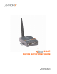
WiBox 2100E Device Server User Guide Part Number 900-351 Revision M August 2013
Intellectual Property © 2013 Lantronix, Inc. All rights reserved. No part of the contents of this book may be transmitted or reproduced in any form or by any means without the written permission of Lantronix. WiBox, DSTni and Lantronix are registered trademarks of Lantronix, Inc. in the United States and other countries. SmartRoam and DeviceInstaller are trademarks of Lantronix, Inc. U.S. Patent 7,309,260. Additional patents pending.
Date Rev. Comments July 2006 F Updated for firmware version 6.1.0.2 April 2007 G Updated for firmware version 6.4 May 2007 H Updated for firmware version 6.5 July 2007 I Updated for firmware version 6.5.0.5 May 2008 J Updated for firmware version 6.6 June 2008 K Minor corrections January 2010 L Updated for firmware version 6.7 and minor corrections. Added new fields: Minimum TX Data Rate, Max TX Failures, and Automatic Host MAC Detection. Added Wireless Status (WS) command.
Table of Contents Intellectual Property _____________________________________________________ Warranty ______________________________________________________________ Contacts ______________________________________________________________ Revision History ________________________________________________________ List of Tables ___________________________________________________________ List of Figures __________________________________________________________ 1: Using This Guide 2 2 2 2 8 8 9 Purpose and
Contents Automatic IP Address Configuration ____________________________________ Static IP Address Configuration ________________________________________ Ethernet Configuration _______________________________________________ Server Configuration ____________________________________________________ Hostlist Configuration ___________________________________________________ Channel 1 and Channel 2 Configuration _____________________________________ Serial Settings _____________________________________________
Contents Send Characters ____________________________________________________ DisConnTime (Inactivity Timeout) __________________________________________ Send Characters _______________________________________________________ Telnet Terminal Type ___________________________________________________ Channel (Port) Password ________________________________________________ WLAN Settings ________________________________________________________ Topology __________________________________________________________
Contents Default Settings (Option 7) _______________________________________________ Channel 1 Configuration ______________________________________________ Channel 2 Configuration ______________________________________________ WLAN Settings _____________________________________________________ Expert Settings _____________________________________________________ Security Settings ____________________________________________________ Exit Configuration Mode _________________________________________________
Contents List of Tables Table 2-1. WiBox 2100E LEDs _________________________________________________ 17 Table 2-2. WiBox 2100E Technical Specifications __________________________________ 18 Table 6-1. BootP/DHCP/AutoIP options __________________________________________ 46 Table 6-2. Standard IP Network Netmasks ________________________________________ 47 Table 7-1. Interface Mode Options ______________________________________________ 50 Table 7-2.
1: Using This Guide Purpose and Audience This guide provides the information needed to configure, use, and update the Lantronix® WiBox® 2100E device server. It is for network administrators, system integrators, and those responsible for installing and maintaining the WiBox 2100E. Chapter Summary The remaining chapters in this guide include: Chapter Description 2: Introduction Describes the main features of the WiBox 2100E and the protocols it supports.
1: Using This Guide B: Binary to Hexadecimal Conversions Provides instructions for converting binary numbers to hexadecimals. C: Compliance Information Provides compliance information. Additional Documentation Visit the Lantronix web site at http://www.lantronix.com/support/documentation.html for the latest documentation and the following additional documentation: Document Description WiBox 2100E Device Server Quick Start Guide Provides instructions for getting your WiBox 2100E up and running.
2: Introduction The WiBox 2100E family of wireless device servers provides serial-to-wireless network connectivity. They enable you to access, control, monitor, or share on an 802.11b/g wireless network virtually any serial device or equipment remotely. The WiBox 2100E device server provides a fully integrated solution that combines an operating system, embedded Web server, full TCP/IP protocol stack with an 802.11b/g transceiver supporting WEP, WPA and 802.
2: Introduction RFID readers Universal Power Supply (UPS) Management units Telecommunications equipment Data display devices Virtually any RS-232, RS-422 4-wire or RS-485 2-wire asynchronous serial device Application Examples The WiBox 2100E has two serial ports and an 802.11b/g transceiver. Each serial port is connected to the serial communication port of a device. The wireless transceiver connects to another wireless device or to an Access Point (AP).
2: Introduction Ad Hoc Network Figure 2-2. Ad Hoc Network Example In the example above, the AP is not present. The PC makes a direct wireless connection with the WiBox 2100E to manage serial devices. Without an AP, it is a peer-to-peer relationship. Serial Tunneling – Infrastructure Figure 2-3. Serial Tunneling Infrastructure Example In the example above, the WiBox 2100E communicates with another device server via the AP.
2: Introduction Ad Hoc WiBox 2100E Connection Figure 2-4. Direct WiBox 2100E-to-WiBox 2100E Connection In the example above, the two WiBox 2100E devices have established an Ad Hoc peer-to-peer relationship. They communicate directly to each other’s serial devices without a PC or an AP. WiBox 2100E with Ethernet With this model, you can select either a wireless or an Ethernet connection. Protocol Support The WiBox 2100E device server uses the TCP/IP protocol stack for network communications.
2: Introduction Serial & Telnet Ports: There are two approaches to accessing Setup Mode. Make a Telnet connection to the network port (9999) or connect a terminal (or a PC running a terminal emulation program) to the unit’s serial port. See Telnet or Serial Port (Setup Mode) Configuration. DeviceInstaller: This utility provides a GUI interface for assigning the IP address, viewing the current configuration, and updating firmware.
2: Introduction Figure 2-5. DB9M DTE Serial Connector Alternatively, you can configure the WiBox 2100E for RS-422 4-wire communications (Figure 2-6) or for RS-485 2-wire communications (Figure 2-7). Figure 2-6. RS-422 4-Wire Pinouts Figure 2-7.
2: Introduction WiBox 2100E Network Interface The back panel of the WiBox 2100E contains a 9-30VDC power plug and an RJ45 (10/100) Ethernet port. Figure 2-8. Network Interface Power Plug RJ45 Ethernet Port (WiBox 2100E only) Ethernet Connector Pinouts Figure 2-9. RJ45 Ethernet Connector LEDs Table 2-1.
2: Introduction LEDs Meaning Port 1 LED: Green, steady on Idle Port 1 LED: Green, blinking Active TCP connection Port 2 LED: Yellow, steady on Idle Port 2 LED: Yellow, blinking Active TCP connection Technical Specifications Table 2-2. WiBox 2100E Technical Specifications CPU, Memory Lantronix® DSTni® EX embedded device server 186 CPU 256 KB zero wait state SRAM 2048 KB Flash Serial Interface Rate is software selectable (300 bps to 921600 bps) Network Interface Wireless 802.
3: Getting Started This chapter describes the procedure for getting your WiBox 2100E device server up and running. Installing the WiBox 2100E Note: For diagrams of the mounting brackets, see A: Mounting Brackets. Complete the following steps to connect and initially configure the WiBox 2100E. Initial configuration is done using the Setup Mode’s Change Setup menu. Figure 3-1. WiBox 2100E Connected for Configuration 1.
3: Getting Started Configuring the WiBox 2100E Two settings are required for the WiBox 2100E to communicate on a wireless network: The Server (0) settings The WLAN (4) settings Note: Due to regulations, the country-specific setting has been removed from the setup menu and Web Manager. We provide a separate utility for changing the Country/Zone setting. The utility is called SetZone and is included in the WiBox 2100E package. It is also available for download from the Lantronix web site.
3: Getting Started Change Telnet/Web Manager Password: Change the Telnet configuration password to prevent unauthorized access to the Change Setup menu and Web Manager. Change Telnet/Web Manager password (N) ? _ Change DHCP Device Name: Change the DHCP name if the network is DHCP-enabled. Case 1: Change DHCP device name (not set) ? (N) Y Enter new DHCP device Name : Enable DHCP FQDN option : (N) ? Case 2: Change DHCP device name (not set) ? (N) N Enable DHCP FQDN option : (N) ? 2.
3: Getting Started Property Description communication partner before passing through messages or not (2 = open/none). Encryption Length of the encryption key and the security strength. WEP64 uses a 40 bits/5 bytes key (option 1). WEP128 uses a 104 bits/13 bytes key (option 2). Change key Select (Y) Yes to modify the currently configured key. Display Key Select (Y) Yes to show the currently configured key/passphrase Key type Indicate whether the new key is in hexadecimal or passphrase format.
3: Getting Started 802.11i/WPA2-Personal : Security suite: 0=none, 1=WEP, 2=WPA, 3=WPA2/802.11i (0) ? 3 Change key (N) ? Y Display key (N) ? Key type 0=hex, 1=passphrase (1) ? Enter key: *********************** Encryption: 0=CCMP, 1=CCMP+TKIP, 2=CCMP+WEP, 3=TKIP, 4=TKIP+WEP (3) ? Property Description Change key Select (Y) Yes to modify the currently configured key. Display key Select (Y) Yes to show the currently configured key/passphrase.
3: Getting Started Viewing the Current Configuration After locating the WiBox 2100E as described in DeviceInstaller Help, you can view its current configuration. To view the WiBox 2100E’s configuration settings: In the right window, click the Device Details tab. The current WiBox 2100E configuration displays: Property Description Name A name to identify the WiBox 2100E. Double-click the field, type the value, and press Enter to complete.
3: Getting Started Property Description Gateway Non-configurable field. Displays the WiBox 2100E’s current gateway. To change the gateway, see 4: Web Manager Configuration or 5: Telnet or Serial Port (Setup Mode) Configuration. Number of COB partitions supported Non-configurable field. Displays the number of COB partitions supported (between 19 and 51). Number of Serial Ports Non-configurable field. Displays the number of ports on the WiBox 2100E. TCP Keepalive Non-configurable field.
4: Web Manager Configuration This chapter describes how to configure the WiBox 2100E device server using the Lantronix Web Manager browser-based configuration tool. The unit’s configuration is stored in nonvolatile memory and is retained without power. The unit performs a reset after the configuration is changed and stored. Accessing Web Manager through a Web Browser 1. Open a standard web browser.
4: Web Manager Configuration The main menu is on the left panel of the Web Manager window. Network Configuration Select Network from the main menu to display the unit's network values. The following sections describe the configurable network parameters. Note: If the IP address is assigned via DHCP, its DHCP settings do not display. Figure 4-2. Network Settings Network Mode Configuration To determine the unit’s network mode: 1. Click Network from the main menu. 2.
4: Web Manager Configuration Automatic IP Address Configuration To assign an IP address and its network configuration automatically: 1. Click Network from the main menu. 2. Select Obtain IP address automatically. 3. Enter the following (as necessary): BOOTP Enable permits the Bootstrap Protocol (BOOTP). The BOOTP server assigns the IP address automatically from a pool of addresses. DHCP Enable permits Dynamic Host Configuration Protocol (DHCP).
4: Web Manager Configuration Ethernet Configuration You must specify the speed and direction of data transmission. To specify how data will be transmitted: 1. On the main menu, click Network. 2. Enter the following (as necessary): Auto Negotiate With this option, the Ethernet port auto-negotiates the speed and duplex with the hardware endpoint to which it is connected. This is the default setting. If this option is not selected, complete the Speed and Duplex fields that become available.
4: Web Manager Configuration Server Configuration The unit’s server values display upon selecting Server from the main menu. The following sections describe the configurable parameters within the Server configuration menu. Figure 4-3. Server Settings Note: Ethernet configuration is not available in Wireless Only mode. To configure the WiBox 2100E’s device server settings: 1. Click Server from the main menu. 2.
4: Web Manager Configuration Advanced ARP Cache Timeout (secs) When the unit communicates with another device on the network, it adds an entry into its ARP table. ARP Cache timeout defines the number of seconds (1-600) before it refreshes this table. TCP Keepalive (secs) TCP Keepalive time defines how many seconds the unit waits during an inactive connection before checking its status. If the unit does not receive a response, it drops that connection. Enter a value between 1 and 65 seconds.
4: Web Manager Configuration Figure 4-4. Hostlist Settings To configure the WiBox 2100E’s hostlist: 1. From the main menu, click the Hostlist tab. 2. Enter or modify the following fields from the Hostlist Settings window: Retry Settings Retry Counter Enter the value for the number of times the WiBox 2100E should attempt to retry connecting to the hostlist. The default setting is 3. Retry Timeout Enter the duration (in milliseconds) the WiBox 2100E should abandon attempting a connection to the hostlist.
4: Web Manager Configuration Serial Settings To configure a channel’s serial settings: 1. From the main menu, click Serial Settings for either Channel 1 or Channel 2 to display the Serial Settings page for the selected channel. Figure 4-5. Channel Serial Settings 2. In the available fields, enter the following information: Channel Disable Serial Port Available on Channel 2 settings only. When selected, disables communication through the serial port.
4: Web Manager Configuration Flow Control Flow control manages data flow between devices in a network to ensure it is processed efficiently. Too much data arriving before a device is prepared to manage it causes lost or retransmitted data. The default setting is None. Baud Rate The unit and attached serial device, such as a modem, must agree on a speed or baud rate to use for the serial connection. Valid baud rates are 300, 600, 1200, 2400, 4800, 9600 (default), 19200, 38400, 57600, 115200, or 230400.
4: Web Manager Configuration At Time of Disconnect Select Yes to clear the input buffer when the network connection to or from the device is disconnected. The default setting is No. Flush Output Buffer (Network to Serial) With Active Connect Select Yes to clear the output buffer with a connection that is initiated from the device to the network. The default setting is No. With Passive Connect Select Yes to clear the output buffer with a connection initiated from the network to the device.
4: Web Manager Configuration Figure 4-6. TCP Connection Settings Connect Mode: Passive Connection Accept Incoming Select Yes to accept incoming connections. Password Required Determines whether a password is required for an incoming passive connection. This field is not available when a password is set for Telnet mode. The default setting is No. Password If Password Required was set to Yes, enter the password for passive connections.
4: Web Manager Configuration Connect Mode: Active Connection Active Connect Select None (default) to disable Active Connect. Otherwise, indicate the connection type from the drop-down list: With Any Character: Attempts to connect when any character is received from the serial port. With Active Mdm Ctrl In: Accepts external connection requests only when the Modem Control In input is asserted. With Start Character: Attempts to connect when it receives a specific start character from the serial port.
4: Web Manager Configuration connects, the unit stops trying to connect to any others. If this connection fails, the unit continues to scroll through the table until it is able to connect to another IP in the host list. The host list is disabled for Manual and Modem Modes. The unit will not accept a data connection from a remote device when the host list option is enabled. LED Select Blink for the status LEDs to blink upon connection, or select None for no LED output.
4: Web Manager Configuration Figure 4-7. UDP Connection Settings 2. In the available fields, enter the following information: Datagram Mode Datagram Type Configures remote IP or network broadcast address and the remote port. Enter 01 for directed or broadcast UDP. The default setting is 00. Accept Incoming Select Yes to accept incoming UDP datagrams. Endpoint Configuration Local Port Enter the local port number. Remote Port Enter the port number of the remote device.
4: Web Manager Configuration 3. When you are finished, click the OK button. 4. On the main menu, click Apply Settings. WLAN Configuration Without adequate protection, a wireless LAN is susceptible to access by unauthorized users.
4: Web Manager Configuration Figure 4-8. WLAN Settings 2. Enter or modify the following fields: Wireless Network Configuration Network Name Enter the name of the wireless network (SSID). The WiBox 2100E connects to this wireless network. Network Type Select Infrastructure or Ad Hoc. Channel Configurable only when Network Type is Ad Hoc. Select from the pulldown menu the radio channel for the Ad Hoc network. The default value is 11.
4: Web Manager Configuration WEP Options Authentication Select an authentication scheme (Open/None or Shared) from the drop-down list. Encryption Select the encryption type (64 bits or 128 bits for WEP) from the dropdown list. 64 bits is the default encryption for WEP. Key Type Select the key type (Hex or Passphrase). Key and Retype Key Enter the Encryption Key in hexadecimal value if Hex is selected as the key type. Enter key as a string if Passphrase is selected as the key type.
4: Web Manager Configuration Note: If Auto Rate Fallback is enabled and a minimum TX data rate other than 1Mbps is configured, the radio will operate in Single Rate Drop mode. This means that if a rate drop becomes necessary, the radio will drop from the maximum rate to the lowest rate, ignoring all rates in between. This reduces the potential number of packet retransmission attempts, because the radio attempts to transmit a packet three times before transitioning to the next lowest TX rate.
5: Telnet or Serial Port (Setup Mode) Configuration You must configure the unit so that it can communicate on a network with your serial device. As an alternative to using a web browser, as described in the previous chapter, you can use the following procedures remotely or locally: Use a Telnet connection to configure the unit over the network. Use a terminal or terminal emulation program to access the serial port locally.
5: Telnet or Serial Port (Setup Mode) Configuration Figure 5-2. Setup Menu Options Change Setup: 0 Server 1 Channel 1 2 Channel 2 4 WLAN 5 Expert 6 Security 7 Defaults 8 Exit without save 9 Save and exit Your choice ? 4. Select an option on the menu by entering the number of the option in the Your choice ? field and pressing Enter. 5. To enter a value for a parameter, type the value and press Enter, or to confirm a current value, just press Enter. 6.
6: Setup Mode: Server Configuration This chapter explains how to configure the network settings. Note: Current values display in parentheses. Server Configuration (Option 0) The unit’s basic network parameters display when you select Server configuration (option 0). Network Mode Select the network mode for the WiBox 2100E device server. Options available are Wired Only, Wireless Only, and Bridging. (For more information on bridging, see 11: Wireless Bridging.
6: Setup Mode: Server Configuration The gateway address must be within the local network. The default setting is N (No), meaning the gateway address has not been set. To set the gateway address, type Y and enter the address. Set Gateway IP Address (N) ? Y Gateway IP addr (000) (000) (000) (000)_ Netmask: Number of Bits for Host Part A netmask defines the number of bits taken from the IP address that are assigned for the host part.
6: Setup Mode: Server Configuration The host attached to the WiBox 2100E may communicate with other CoBos devices on the wireless network using the Lantronix Configuration Access Protocol (LCAP). This service is available on server port number 0x77FE (30718) and is fixed. When the WiBox 2100E is in bridging mode, the LCAP port number is modifiable so that the LCAP service is available on the wired interface for WiBox 2100E configuration. See 11: Wireless Bridging for more information.
7: Setup Mode: Channel Configuration This chapter explains how to configure the serial port. Notes: Current values display in parenthesis. You must enter some values in hexadecimal notation. (See B: Binary to Hexadecimal Conversions on page 88.) Channel 1 (Option 1) Select Channel 1 (option 1) from the Change Setup menu to define how the serial port responds to network and serial communications. The following sections describe the configurable parameters within the Channel configuration menu.
7: Setup Mode: Channel Configuration I/F (Interface) Mode The Interface (I/F) Mode is a bit-coded byte entered in hexadecimal notation. The default setting is 4C. Note: RS-422 4-wire and RS-485 2-wire are available on Channel 2 only. I/F Mode (4C) ? _ The following table displays available I/F Mode options: Note: All bit positions in the table that are blank represent “don’t care” bits for that particular option; they can be set to either a 0 or 1 value. Table 7-1.
7: Setup Mode: Channel Configuration Flow Flow control sets the local handshaking method for stopping serial input/output. The default setting is 00. Flow (00) ? _ Use the following table to select flow control options: Table 7-3. Flow Control Options Flow Control Option Hex No flow control 00 XON/XOFF flow control 01 Hardware handshake with RTS/CTS lines 02 XON/XOFF pass characters to host 05 Port Number The setting represents the source port number in TCP connections.
7: Setup Mode: Channel Configuration Connect Mode Connect Mode defines how the unit makes a connection, and how it reacts to incoming connections over the network. The default setting is C0. ConnectMode (C0) ? _ Enter Connect Mode options in hexadecimal notation. Note: All bit positions in the table that are blank represent “don’t care” bits for that particular option; they can be set to either a 0 or 1 value. Table 7-5.
7: Setup Mode: Channel Configuration a) Incoming Connection Never Accept Incoming Rejects all external connection attempts. Accept with active Modem Control In Accepts external connection requests only when Modem Control In input is asserted. Cannot be used with Modem Mode. Always Accept Accepts any incoming connection when a connection is not already established. Default setting.
7: Setup Mode: Channel Configuration uses the internally stored remote IP address to provide the most significant bytes of the IP address. If the IP address entered is 0.0.0.0/0, the device server enters Monitor Mode. For example, if the remote IP address already configured in the unit is 129.1.2.3, then an example command string would be C3/7. (This would connect to 129.1.2.3 and port 7.) You may also use a different ending for the connection string. For example, C50.1/23 would connect you to 129.1.50.
7: Setup Mode: Channel Configuration Autostart (Automatic Connection) If you enable Autostart, the unit automatically connects to the remote IP address and remote port specified when the firmware starts. Hostlist If you enable this option, the device server scrolls through the hostlist until it connects to a device listed in the hostlist table. Once it connects, the unit stops trying to connect to any others.
7: Setup Mode: Channel Configuration 4. For Retrycounter, enter the number of times the WiBox 2100E device server should try to make a good network connection to a hostlist entry that it has successfully ARPed. The range is 1-15, with the default set to 3. 5. For Retrytimeout, enter the number of seconds the unit should wait before failing an attempted connection. The time is stored as units of milliseconds in the range of 10-65535. The default setting is 250.
7: Setup Mode: Channel Configuration Table 7-7. Modem Mode Messages Message Meaning Full Verbose OK Command was executed without error. CONNECT A network connection has been established. NO CARRIER A network connection has been closed. RING n.n.n.n. A remote device, having IP address n.n.n.n, is connecting to this device.
7: Setup Mode: Channel Configuration Table 7-8. Modem Mode Commands Modem Mode Command Function ATDTx.x.x.x,pppp or ATDTx.x.x.x/pppp or ATDTx.x.x.x:pppp Makes a connection to an IP address (x.x.x.x) and a remote port number (pppp). ATDTx.x.x.x Makes a connection to an IP address (x.x.x.x) and the remote port number defined within the unit. ATD0.0.0.0 Forces the unit into Monitor Mode if a remote IP address and port number are defined within the unit.
7: Setup Mode: Channel Configuration Auto Increment Source Port Auto increment source port (N) ? _ Y (Yes) auto increment the source port. The WiBox 2100E increments the port number used with each new connection. Remote IP Address This is the destination IP address used with an outgoing connection. Remote IP Address : (000) (000) (000) (000)_ Note: This option does not display when Hostlist is enabled from the ConnectMode prompt (see Connect Mode on page 52 for more information).
7: Setup Mode: Channel Configuration Table 7-9. Disconnect Mode Options Disconnect Mode Option 7 Disconnect when Modem Control In is not (6) asserted 1 Ignore Modem Control In 0 Telnet Com Port Cntrl and terminal type setup Channel (port) password Hard disconnect (1) 6 5 4 3 1 0 1 (2) 1 (3) 0 Disable hard disconnect 1 State LED off with connection Disconnect with EOT (^D) 2 (4) 1 (5) 1 (1) The WiBox 2100E sends the "Terminal Type" upon an outgoing connection.
7: Setup Mode: Channel Configuration Function 7 Clear when the network connection to or from the device is disconnected 6 5 4 3 2 1 0 1 Output Buffer (Network to Serial) Clear with a connection initiated from the device to the network 1 Clear with a connection initiated from the network to the device 1 Clear when the network connection to or from the device is disconnected 1 Alternate Packing Algorithm (Pack Control) Enable 1 Pack Control The packing algorithms define how and when packet
7: Setup Mode: Channel Configuration Option Send Immediately After Send chars 7 6 5 4 3 2 1 0 1 Packing Interval Packing Interval defines how long the unit should wait before sending accumulated characters. This wait period is between successive network segments containing data. For alternate packing, the default interval is 12 ms.
7: Setup Mode: Channel Configuration Telnet Terminal Type This parameter displays only if you enabled the terminal type option in Disconnect Mode. With this option enabled, you can use the terminal name for the Telnet terminal type. Enter only one name. With terminal type option enabled, the unit also reacts to the EOR (end of record) and binary options, useful for applications like terminal emulation to IBM hosts.
7: Setup Mode: Channel Configuration Security suite 0=none, 1=WEP, 2=WPA, 3=WPA2/802.11i (0) ? _ WEP Authentication: 0=open/none, 1=shared (1) ? Encryption: 1=WEP64, 2=WEP128 (2) ? Change Key (N) ? Y Display key (N) ? Key type 0=hex, 1=passphrase (0) ? Enter Key: **-**-**-**-**-**-**-**-**-**-**-**-** TX Key Index (1) ? Authentication Select whether the encryption keys are matched (1 = shared) with those of the communication partner before passing through messages or not (2 = open/none).
7: Setup Mode: Channel Configuration Encryption Set the type to the minimum required security level. The “+” sign indicates that the group (broadcast) encryption method is different from the pairwise (unicast) encryption (WEP and TKIP). 802.11i/WPA2-Personal Change key (N) ? Y Display key (N) ? Key type 0=hex, 1=passphrase (1) ? Enter key: *********************** Encryption: 0=CCMP, 1=CCMP+TKIP, 2=CCMP+WEP, 3=TKIP, 4=TKIP+WEP (3) ? Change key Select (Y) Yes to modify the currently configured key.
7: Setup Mode: Channel Configuration rates in between. This reduces the potential number of packet retransmission attempts, because the radio attempts to transmit a packet three times before transitioning to the next lowest TX rate. Note: If the Minimum TX Data Rate is set for 54 Mbps for the minimum and maximum, the auto fallback capability is eliminated. Enable Power Management This allows the software to turn off the radio when expecting not to receive or transmit soon.
8: Setup Mode: Advanced Settings Expert Settings (Option 5) Note: You can change these settings using Telnet or serial connections only, not Web Manager. Caution: Only an expert should change these parameters. You must definitely know the consequences the changes may have. Figure 8-1.
8: Setup Mode: Advanced Settings TCP Keepalive time in seconds This option allows you to change how many seconds the unit waits during a silent connection before attempting to see if the currently connected network device is still on the network. If the unit gets no response, it drops that connection. The default setting is 45.
8: Setup Mode: Advanced Settings TCP Re-transmission Timeout This feature allows the configuration of the desired TCP re-transmission timeout value. If the ACK is not received for a packet sent from the WiBox device, then the unit will retransmit the data. The valid range is 500-4000 msec. TCP Re-transmission Timeout (500 - 4000) (ms): (500) ? Enable Alternate MAC If necessary, enable the alternate MAC address (if specified in the OEM setup record). The default setting is N (No).
8: Setup Mode: Advanced Settings Disable SNMP For security purposes, disable SNMP (if required) on the WiBox 2100E unit. The current setting displays in parentheses. Disable SNMP (N) ? _ SNMP Community Name The SNMP Community Name is a required field for NMS to read or write to a device. Enter a string of 1 to 13 characters. SNMP Community Name (public): _ The default entry is public. The current value displays in parentheses.
8: Setup Mode: Advanced Settings Disable Web Setup (N) ? _ Disable ECHO Ports This setting controls whether port 7 echoes characters it receives. Disable ECHO ports (Y) ? _ Enable Encryption Rijndael is the block cipher algorithm chosen by the National Institute of Science and Technology (NIST) as the Advanced Encryption Standard (AES) to be used by the US government. The WiBox 2100E supports 128-, 192-, and 256-bit encryption key lengths.
8: Setup Mode: Advanced Settings Enable Enhanced Password (Y) ? _ The Y (Yes) option allows an extended security password of 16-characters for protecting Telnet access. Default Settings (Option 7) Select 7 Defaults from the Change Setup menu to reset the unit’s Channel 1 configuration, Channel 2 configuration, Security, and Expert settings to the factory default settings. The server configuration settings for IP address, gateway IP address, and netmask remain unchanged.
8: Setup Mode: Advanced Settings Network Name LTRX_IBSS Channel 11 Security 0 (none) TX Data Rate Auto Fallback 1 1 TX Data Rate Minimum TX Data Rate Max Failures 1 (auto) 54 Mbps 1 1 1 Mbps 6 (failed attempts) Enable Power Management N (No) Enable Soft AP Roaming N (No) Expert Settings TCP Keepalive 45 (seconds) ARP Cache Timeout 600 (seconds) CPU Performance Regular Disable Monitor Mode N (No) HTTP Port Number 80 MTU Size 1400 TCP re-transmission Timeout 500 (msec) Enable
8: Setup Mode: Advanced Settings Disable Web Setup N (No) Disable ECHO ports Y (Yes) Enable Encryption N (No) Enable Enhanced password N (No) Exit Configuration Mode To exit Setup Mode, do one of the following: To save all changes and reboot the device, select option 9 Save and exit from the Change Setup menu. or To exit the configuration mode without saving any changes or rebooting, select option 8 Exit without save from the Change Setup menu.
9: Monitor Mode Monitor Mode is a command-line interface used for diagnostic purposes. There are two ways to enter Monitor Mode: locally via the serial port or remotely via the network. Entering Monitor Mode via the Serial Port To enter Monitor Mode locally: 1. Follow the same steps used for setting the serial configuration parameters (see 5:Telnet or Serial Port (Setup Mode) Configuration). 2. Instead of typing three x keys, however: 3. Type zzz to enter Monitor Mode with network connections. 4.
9: Monitor Mode Command Command Name Function PI x.x.x.x Ping Pings unit with IP address x.x.x.x to check device status. AT ARP Table Shows the unit’s ARP table entries. TT TCP Connection Table Shows all incoming and outgoing TCP connections. NC Network Connection Shows the unit’s current IP address, gateway, subnet mask, and DNS server. RS Reset Resets the unit. QU Quit Exits diagnostics mode. G0, G1, ....
9: Monitor Mode Note: Entering any of the commands listed above generates one of the following command response codes: Table 9-2.
10: Updating Firmware This chapter explains how to obtain and update the unit’s firmware. Obtaining Firmware Obtain the most up-to-date firmware and release notes for the unit from the Lantronix web site (www.lantronix.com) or by using anonymous FTP (ftp.lantronix.com/pub). Reloading Firmware There are several ways to update the unit’s internal operational code (*ROM) via TFTP or via the serial port. You can also update the unit’s internal web interface (*COB) via TFTP.
10: Updating Firmware Figure 10-1. TFTP Window After the firmware has been loaded and stored, which takes approximately 8 seconds, the unit performs a power reset. Using TFTP: Command Line Interface To download new firmware from a computer: 1. Enter the following from a TFTP command line interface: tftp –i put The following examples demonstrate the TFTP command sequence to download the .rom file and the .cob file: tftp –i 192.168.1.
10: Updating Firmware To recover firmware: 1. Connect the COM interface of your PC to serial port 1 of the WiBox 2100E device server. 2. Start DeviceInstaller. If your PC has more than one network adapter, a message displays. Select an adapter and click the OK button. 3. From the Tools menu, select Advanced/Recover Firmware. The Serial Port Firmware Upgrade window displays. 4. For Port on PC, enter the COM port on the PC that is connected to the serial port of the Lantronix unit. 5.
11: Wireless Bridging Note: The WiBox 2100E device server with firmware version 6.2 and later will support bridging. Bridging allows a host, connected on the WiBox 2100E’s wired Ethernet interface, to be accessible over the wireless network (via the WiBox 2100E). To initialize the bridging feature: 1. Configure the WiBox 2100E’s wireless settings. See WLAN Configuration. 2. Enable bridging in Setup Mode. See Network Mode. 3. Set up the wired host connected to the WiBox 2100E’s Ethernet port.
11: Wireless Bridging Method 3 As an alternative to configuring through the wired interface, connect a device through the WiBox 2100E’s serial port. For more information on configuration through the serial port, see 5:Telnet or Serial Port (Setup Mode) Configuration.
12: Troubleshooting This chapter discusses how you can diagnose and fix errors quickly without having to contact a dealer or Lantronix. It helps to connect a terminal to the serial port while diagnosing an error to view summary messages that may be displayed. When troubleshooting, always ensure that the physical connections (power cable, network cable, and serial cable) are secure. Note: Some unexplained errors might be caused by duplicate IP addresses on the network.
12: Troubleshooting Problem/Message Reason Solution Note: With 6.x.x.x firmware and Infrastructure Network Name (SSID) is set blank or different from the Ad Hoc name and the WiBox 2100E is associated to Infrastructure Network Set the Infrastructure Network Name (SSID) to the same name as the Ad Hoc name. later, there is only one setting for Network Name; it is the same for both Infrastructure and Ad Hoc modes.
12: Troubleshooting Problem/Message Reason The device server is not communicating with the serial device it is attached to. The most likely reason is the The serial settings for the serial wrong serial settings were chosen. device and the device server must match. The default serial settings for the device server are RS-232, 9600 baud, 8 character bits, no parity, 1 stop bit, no flow control. When you try to enter the Setup Mode on the device server via the serial port, you get no response.
12: Troubleshooting Technical Support If you are experiencing an error that is not described in this chapter, or if you are unable to fix the error, contact Technical Support. Technical Support US Check our online knowledge base or send a question to Technical Support at http://www.lantronix.com/support. Phone: (949) 453-3990 Technical Support Europe, Middle East, and Africa Phone: +33 (0)1 39 30 41 72 Germany: +49 (0) 180 500 13 53 Email: eu_techsupp@lantronix.com or eu_support@lantronix.
A: Mounting Brackets The following drawings provide dimensions of the brackets for mounting the WiBox 2100E device server.
B: Binary to Hexadecimal Conversions Many of the unit’s configuration procedures require assembling a series of options (represented as bits) into a complete command (represented as a byte). Convert the resulting binary value to a hexadecimal representation. Converting Binary to Hexadecimal Following are two simple ways to convert binary numbers to hexadecimals. Conversion Table Hexadecimal digits have values ranging from 0 to F, which are represented as 0-9, A (for 10), B (for 11), etc.
Binary to Hexadecimal Conversions 3. Click Bin (Binary), and type the number to convert. 4. Click Hex. The hexadecimal value displays.
C: Compliance Compliance Information Manufacturer’s Name & Address: Lantronix, Inc. at 167 Technology, Irvine, CA 92618 USA Declares that the following product: Product Name: WiBox® Device Server Model: WBX2100E Conforms to the following standards or other normative documents: Safety: UL 60950-1 CAN/CSA-C22.2 No.
Compliance RoHS Notice All Lantronix products in the following families are China RoHS-compliant and free of the following hazardous substances and elements: • • Lead (Pb) Cadmium (Cd) Product Family Name UDS1100 and 2100 EDS MSS100 IntelliBox XPress DR & XPress-DR+ SecureBox 1101 & 2101 WiBox 2100E UBox MatchPort SLC XPort WiBox SLB SLP SCS SLS DSC • • • • • Mercury (Hg) Hexavalent Chromium (Cr (VI)) Toxic or hazardous Substances and Elements Lead Mercury Cadmium Hexavalent (Pb) (Hg) (Cd) Chromium
Compliance If this equipment does cause harmful interference to radio or television reception, which can be determined by turning the equipment off and on, the user is encouraged to try to correct the interference by one or more of the following measures: Reorient or relocate the receiving antenna. Increase the separation between the equipment and receiver. Connect the equipment into an outlet on a circuit different from that to which the receiver is connected.
Compliance Europe – R&TTE Directive 99/5/EC, Wireless Notice This product is designated as a Class 2 type radio device that utilizes non-harmonized frequencies and power levels for Europe. It is marked with the following warning symbol to bring to your attention to the fact it might not be legal to use this product in every country. In most cases this product has already been granted permission for use from individual countries in Europe.