
Technical Specs
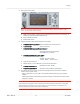
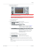
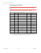
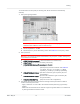
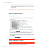
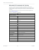
Table Of Contents
- Important Notice
- Safety and Hazards
- Limitation of Liability
- Contents
- List of Tables
- List of Figures
- 1: Introduction
- 2: Electrical Specifications
- 3: RF Specifications
- 4: Power
- 5: Software Interface
- 6: Mechanical and Environmental Specifica- tions
- 7: Regulatory Compliance and Industry Certifi- cations
- A: Antenna Specification
- B: Design Checklist
- C: Testing
- AT Command Entry Timing Requirement
- Acceptance Testing
- Certification Testing
- Production Testing
- Functional Production Test
- Quality Assurance Testing
- Suggested Testing Equipment
- Testing Assistance Provided by Lantronix, Inc.
- IOT/Operator Testing
- Extended AT Commands for Testing
- D: Packaging
- E: References
- F: Acronyms

Rev 5 May.21
78
41113694
Product
Technical
Specification
·
The Signal Generator power level can be adjusted and new limits found if the
radiated test needs greater signal strength.
·
Monitor these limits during mass-production ramp-up to determine if further adjust-
ments are needed.
Note: The value measured from the DUT is significantly influenced by the test setup and DUT
design (host RF cabling loss, antenna efficiency and pattern, test antenna efficiency and pattern,
and choice of shield box).
GNSS RF Receive Path Test
The GNSS receive path uses either the dedicated GNSS connector or the shared
Diversity/MIMO/GNSS connector.
To test the GNSS receive path:
1.
Inject a carrier signal at -110 dBm, frequency 1575.52 MHz into the GNSS Rx path at
the connector. (Note that this frequency is 100 kHz higher than the actual GPS L1
center frequency.)
2.
Test the signal carrier-to-noise level at the GNSS receiver:
a.
AT!ENTERCND=”<password>” (Unlock extended AT command set.)
b.
AT!DAFTMACT (Put modem into factory test mode.)
c.
AT!DACGPSTESTMODE=1 (Start CGPS diagnostic task.)
d.
AT!DACGPSSTANDALONE=1 (Enter standalone RF mode.)
e.
AT!DACGPSMASKON (Enable log mask.)
f.
AT!DACGPSCTON (Return signal-to-noise and frequency measurements.)
g.
Repeat AT!DACGPSCTON five to ten times to ensure the measurements are
repeatable and stable.
3.
Leave the RF connection to the embedded module intact, and turn off the signal
generator.
4.
Take several more !DACGPSCTON readings. This will demonstrate a 'bad' signal in
order to set limits for testing, if needed. This frequency offset should fall outside of the
guidelines in the note below, which indicates that the CtoN result is invalid.
5.
(Optional) Turn the signal generator on again, and reduce the level to -120dBm. Take
more
!DACGPSCTON readings and use these as a reference for what a marginal/poor
signal would be.
Note: The response to
AT!DACGPSCTON
for a good connection should show CtoN within 58 +/-
5dB and Freq (frequency offset) within 100000 Hz +/- 5000 Hz .
Quality Assurance Testing
Note: QA is an ongoing process based on random samples from a finished batch of devices.
The quality assurance tests that you perform on your finished products should be
designed to verify the performance and quality of your devices.