
Technical Specs
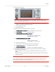
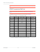
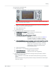
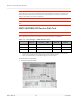
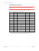
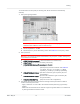
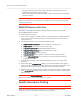
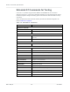
Table Of Contents
- Important Notice
- Safety and Hazards
- Limitation of Liability
- Contents
- List of Tables
- List of Figures
- 1: Introduction
- 2: Electrical Specifications
- 3: RF Specifications
- 4: Power
- 5: Software Interface
- 6: Mechanical and Environmental Specifica- tions
- 7: Regulatory Compliance and Industry Certifi- cations
- A: Antenna Specification
- B: Design Checklist
- C: Testing
- AT Command Entry Timing Requirement
- Acceptance Testing
- Certification Testing
- Production Testing
- Functional Production Test
- Quality Assurance Testing
- Suggested Testing Equipment
- Testing Assistance Provided by Lantronix, Inc.
- IOT/Operator Testing
- Extended AT Commands for Testing
- D: Packaging
- E: References
- F: Acronyms

Rev 5 May.21
77
41113694
Testing
To test the DUT’s receive path (or diversity path, while connected to the diversity
antenna):
1.
Set up the signal generator:
Note: This procedure describes steps using the Agilent 8648C signal generator—the
Rohde & Schwarz SML03 is shown for reference only.
a.
Set the amplitude to -70 dBm
b.
Set the frequency for the band being tested. See Table 3-4 for frequency values.
2.
Set up the DUT:
Warning: The maximum RF power level allowable on any RF port is +10dBm—damage may
occur if this level is exceeded.
a.
AT!ENTERCND=”<password>” (Unlock extended AT command set.)
b.
AT!DAFTMACT (Put modem into factory test mode.)
c.
AT!DARCONFIG=0,3,<bandValue>,<channel>,<lte_bw>
(e.g. AT!DARCONFIG=0,3,1,18300,3)
(Set frequency band and channel. See Table 3-4
for values. <lte_bw>: 0 (1.4 MHz), 1 (3 MHz),
2 (5 MHz), 3 (10 MHz), 4 (15 MHz), 5(20 MHz))
d.
AT!DAGFTMRXAGC=0,3,0,0
(Set LNA to maximum gain on primary Rx, and
get the RSSI.)
e.
AT!DAGFTMRXAGC=0,3,0,1 (Set the LNA to maximum gain on Diversity Rx,
and get the RSSI.)
f.
AT!DARCONFIGDROP=0,3 (Drop the current LTE configuration.)
3.
Test limits— Run ten or more good DUTs through this test procedure to obtain a
nominal received power value.
·
Apply a tolerance of ±5 to 6 dB to each measurement (assuming a good setup
design).
·
Make sure the measurement is made at a high enough level that it is not influenced
by DUT-generated and ambient noise.