
Technical Specs
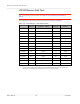
Table Of Contents
- Important Notice
- Safety and Hazards
- Limitation of Liability
- Contents
- List of Tables
- List of Figures
- 1: Introduction
- 2: Electrical Specifications
- 3: RF Specifications
- 4: Power
- 5: Software Interface
- 6: Mechanical and Environmental Specifica- tions
- 7: Regulatory Compliance and Industry Certifi- cations
- A: Antenna Specification
- B: Design Checklist
- C: Testing
- AT Command Entry Timing Requirement
- Acceptance Testing
- Certification Testing
- Production Testing
- Functional Production Test
- Quality Assurance Testing
- Suggested Testing Equipment
- Testing Assistance Provided by Lantronix, Inc.
- IOT/Operator Testing
- Extended AT Commands for Testing
- D: Packaging
- E: References
- F: Acronyms

Rev 5 May.21
75
41113694
Testing
Note: This procedure describes steps using the Agilent 8648C signal generator—the
Rohde & Schwarz SML03 is shown for reference only.
a. Set the amplitude to:
· -80 dBm
b. Set the frequency for the band being tested. See Table 3-3 on page 74 for
frequency values.
2.
Set up the DUT:
Warning: The maximum RF power level allowable on any RF port is +10dBm—damage may
occur if this level is exceeded.
a. AT!ENTERCND=”<password>” (Unlock extended AT command set.)
b. AT!DAFTMACT (Put modem into factory test mode.)
c. AT!DARCONFIG=0,1,<bandValue>,<channel>
(e.g. AT!DARCONFIG=0,1,2,9400)
(Set frequency band and channel.
See Table 3-3 for values.)
d. AT!DAGFTMRXAGC=0,1,0,0
(Set LNA to maximum gain on primary Rx, and
get the RSSI.)
e. AT!DAGFTMRXAGC=0,1,0,1
(Set LNA to maximum gain on Diversity Rx, and
get the RSSI.)
f. AT!DARCONFIGDROP=1 (Drop the current UMTS configuration.)
3.
Test limits— Run ten or more good DUTs through this test procedure to obtain a
nominal received power value.
·
Apply a tolerance of ±5 to 6 dB to each measurement (assuming a good setup
design).
·
Make sure the measurement is made at a high enough level that it is not influenced
by DUT-generated and ambient noise.
·
The Signal Generator power level can be adjusted and new limits found if the
radiated test needs greater signal strength.
·
Monitor these limits during mass-production ramp-up to determine if further adjust-
ments are needed.
Note: The value measured from the DUT is significantly influenced by the test setup and DUT
design (host RF cabling loss, antenna efficiency and pattern, test antenna efficiency and pattern,
and choice of shield box).