
Technical Specs
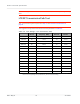
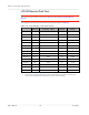
Table Of Contents
- Important Notice
- Safety and Hazards
- Limitation of Liability
- Contents
- List of Tables
- List of Figures
- 1: Introduction
- 2: Electrical Specifications
- 3: RF Specifications
- 4: Power
- 5: Software Interface
- 6: Mechanical and Environmental Specifica- tions
- 7: Regulatory Compliance and Industry Certifi- cations
- A: Antenna Specification
- B: Design Checklist
- C: Testing
- AT Command Entry Timing Requirement
- Acceptance Testing
- Certification Testing
- Production Testing
- Functional Production Test
- Quality Assurance Testing
- Suggested Testing Equipment
- Testing Assistance Provided by Lantronix, Inc.
- IOT/Operator Testing
- Extended AT Commands for Testing
- D: Packaging
- E: References
- F: Acronyms

Rev 5 May.21
74
41113694
Product
Technical
Specification
Note: The module has a nominal output power of +23 dBm
±
1 dB in LTE mode. However, the value
measured by the power meter is significantly influenced (beyond the stated
±
1 dB output power
tolerance) by the test setup (host RF cabling loss, antenna efficiency and pattern, test antenna
efficiency and pattern, and choice of shield box).
Note: When doing the same test over the air in an RF chamber, values are likely to be significantly
lower.
UMTS (WCDMA) RF Receive Path Test
Note: This procedure segment is performed in Step 12 of Production Test Procedure on page 69.
The suggested test procedure that follows uses the parameters in Table 3-3.
Table 3-3:
Test Settings — UMTS Receive Path
Band # Frequency
a
(MHz) Band ID Channel
b
1900 MHz Band 2 1961.2 15
c
9400
1700 MHz Band 4 2133.7 28 1413
850 MHz Band 5 882.7 22 4183
a. Receive frequencies shown are 1.2 MHz offset from center
b. Channel value used by the !DARCONFIG command (!DARCONFIG uses uplink (Tx) channel at the
center of the corresponding band (rounded down), for both Tx and Rx testing).
c. Either 15 (WCDMA1900A) or 16 (WCDMA1900B) may be used for testing.
To test the DUT’s receive path:
1.
Set up the signal generator: