
Technical Specs
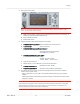
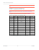
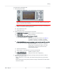
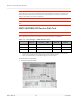
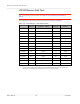
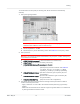
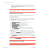
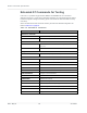
Table Of Contents
- Important Notice
- Safety and Hazards
- Limitation of Liability
- Contents
- List of Tables
- List of Figures
- 1: Introduction
- 2: Electrical Specifications
- 3: RF Specifications
- 4: Power
- 5: Software Interface
- 6: Mechanical and Environmental Specifica- tions
- 7: Regulatory Compliance and Industry Certifi- cations
- A: Antenna Specification
- B: Design Checklist
- C: Testing
- AT Command Entry Timing Requirement
- Acceptance Testing
- Certification Testing
- Production Testing
- Functional Production Test
- Quality Assurance Testing
- Suggested Testing Equipment
- Testing Assistance Provided by Lantronix, Inc.
- IOT/Operator Testing
- Extended AT Commands for Testing
- D: Packaging
- E: References
- F: Acronyms

Rev 5 May.21
73
41113694
Testing
To test the DUT’s transmitter path:
1.
Set up the power meter:
Note: This procedure describes steps using the “Power Meter: Gigatronics 8651A” (with
Option 12 and Power Sensor 80701A).
a. Make sure the meter has been given sufficient time to warm up, if necessary, to
enable it to take accurate measurements.
b. Zero-calibrate the meter.
c. Enable MAP mode.
2.
Prepare the DUT using the following AT commands:
a. AT!ENTERCND=”<password>” (Unlock extended AT command set.)
b. AT!DAFTMACT (Enter test mode.)
c. AT!DARCONFIG=0,3,<bandValue>,<channel>,<lte_bw>
(e.g. AT!DARCONFIG=0,3,1,18300,3)
(Set frequency band and channel. See Table 3-1
for values. <lte_bw>: 0 (1.4 MHz), 1 (3 MHz),
2 (5 MHz), 3 (10 MHz), 4 (15 MHz), 5(20 MHz))
d. AT!DALTXCONTROL=0,1,<tx_pwr>,<waveform>,<mod>,<ns_val>,<num_RB>,<start_RB>
(e.g. AT!DALTXCONTROL=0,1,10,1,0,1,12,19)
(Set LTE Tx power level, waveform, modulation
and NS value. Programs PA range, LUT index,
and digital gain to reach Tx power level with
power limiting enabled.)
e. Take the measurement.
f. Repeat steps c–e with different Tx power levels if desired.
g. AT!DALTXCONTROL=0,0 (Disable Tx power control.)
h. AT!DARCONFIGDROP=3 (Drop the current LTE configuration.)
3.
Test limits— Run ten or more good DUTs through this test procedure to obtain a
nominal output power value.
·
Apply a tolerance of ±5 to 6 dB to each measurement (assuming a good setup
design).
·
Monitor these limits during mass-production ramp-up to determine if further adjust-
ments are needed.