
Technical Specs
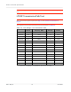
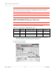
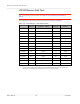
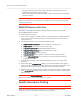
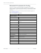
Table Of Contents
- Important Notice
- Safety and Hazards
- Limitation of Liability
- Contents
- List of Tables
- List of Figures
- 1: Introduction
- 2: Electrical Specifications
- 3: RF Specifications
- 4: Power
- 5: Software Interface
- 6: Mechanical and Environmental Specifica- tions
- 7: Regulatory Compliance and Industry Certifi- cations
- A: Antenna Specification
- B: Design Checklist
- C: Testing
- AT Command Entry Timing Requirement
- Acceptance Testing
- Certification Testing
- Production Testing
- Functional Production Test
- Quality Assurance Testing
- Suggested Testing Equipment
- Testing Assistance Provided by Lantronix, Inc.
- IOT/Operator Testing
- Extended AT Commands for Testing
- D: Packaging
- E: References
- F: Acronyms

Rev 5 May.21
72
41113694
Product
Technical
Specification
Note: When doing the same test over the air in an RF chamber, values are likely to be significantly
lower.
LTE RF Transmission Path Test
Note: This procedure segment is performed in Step 11 of the Production Test Procedure on
page 69.
The suggested test procedure that follows uses the parameters in Table 3-2..
Table 3-2:
Test Settings — LTE Transmission Path
Band # Frequency
(MHz) Band ID Channel
a
1900 MHz B2 1880.0 43 18900
1700 MHz B4 1732.5 42 20175
850 MHz B5 836.5 45 20525
2600 MHz B7 2535.0 35 21100
700 MHz B12 707.5 50 23095
700 MHz B13 782.0 36 23230
700 MHz B14 793.0 51 23330
1900 MHz B25 1882.5 61 26365
850 MHz B26 831.5 62 26865
2500 MHz B41 2593.0 76 40620
3500 MHz B42 3500.0 77 42590
3700 MHz B43 3700.0 88 44590
3600 MHz B48 3625.0 96 55990
1700 MHz B66 1745.0 83 132322
600 MHz B71 680.5 97 133297
a. Channel value used by the !DARCONFIG command (!DARCONFIG uses uplink (Tx) channel at the
center of the corresponding band (rounded down), for both Tx and Rx testing).