
Technical Specs
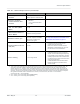
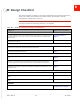
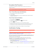
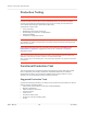
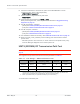
Table Of Contents
- Important Notice
- Safety and Hazards
- Limitation of Liability
- Contents
- List of Tables
- List of Figures
- 1: Introduction
- 2: Electrical Specifications
- 3: RF Specifications
- 4: Power
- 5: Software Interface
- 6: Mechanical and Environmental Specifica- tions
- 7: Regulatory Compliance and Industry Certifi- cations
- A: Antenna Specification
- B: Design Checklist
- C: Testing
- AT Command Entry Timing Requirement
- Acceptance Testing
- Certification Testing
- Production Testing
- Functional Production Test
- Quality Assurance Testing
- Suggested Testing Equipment
- Testing Assistance Provided by Lantronix, Inc.
- IOT/Operator Testing
- Extended AT Commands for Testing
- D: Packaging
- E: References
- F: Acronyms

Rev 5 May.21
70
41113694
Product
Technical
Specification
8.
Unlock the extended AT command set. (Note: Use AT!ENTERCND? to check
command syntax, which is SKU-dependent.):
·
AT!ENTERCND=”<password>”
9.
Put the module in diagnostic/factory test mode:
·
AT!DAFTMACT
10.
Communicate with the SIM using +CPIN or +CIMI.
When performing RF tests, use a test platform as described in Suggested Testing
Equipment on page 79.
11.
Test RF transmission, if desired:
·
(UMTS) See UMTS (WCDMA) RF Transmission Path Test on page 70.
·
(LTE) See LTE RF Transmission Path Test on page 72
12.
Test RF reception, if desired:
·
(UMTS) See UMTS (WCDMA) RF Receive Path Test on page 74.
·
(LTE) See LTE RF Receive Path Test on page 76.
13.
Test standalone GNSS functionality— See GNSS RF Receive Path Test on page 78.
14.
Drive Full_Card_Power_Off# low (or leave floating) and confirm that the module
powers down:
·
Windows systems—The Lantronix, Inc. items under the Ports (COM & LPT) entry
in Device Manager disappear as the module powers off.
UMTS (WCDMA) RF Transmission Path Test
Note: This procedure segment is performed in Step 11 of the Production Test Procedure on
page 69.
The suggested test procedure that follows uses the parameters in Table 3-1.
Table 3-1: Test Settings — UMTS Transmission Path
Band Frequency
(MHz) Band ID
Channel
a
1900 MHz Band 2 1880.0 15
b
9400
1700 MHz Band 4 1732.6 28 1413
850 MHz Band 5 836.6 22 4183
a. Channel values shown are at the center of the corresponding bands.
Channel value used by the !DARCONFIG command (!DARCONFIG uses uplink (Tx) channel at the
center of the corresponding band (rounded down), for both Tx and Rx testing).
b. Either 15 (WCDMA1900A) or 16 (WCDMA1900B) may be used for testing.
To test the DUT’s transmitter path: