
Technical Specs
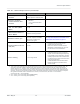
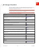
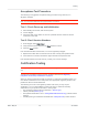
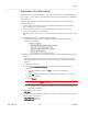
Table Of Contents
- Important Notice
- Safety and Hazards
- Limitation of Liability
- Contents
- List of Tables
- List of Figures
- 1: Introduction
- 2: Electrical Specifications
- 3: RF Specifications
- 4: Power
- 5: Software Interface
- 6: Mechanical and Environmental Specifica- tions
- 7: Regulatory Compliance and Industry Certifi- cations
- A: Antenna Specification
- B: Design Checklist
- C: Testing
- AT Command Entry Timing Requirement
- Acceptance Testing
- Certification Testing
- Production Testing
- Functional Production Test
- Quality Assurance Testing
- Suggested Testing Equipment
- Testing Assistance Provided by Lantronix, Inc.
- IOT/Operator Testing
- Extended AT Commands for Testing
- D: Packaging
- E: References
- F: Acronyms

Rev 5 May.21
69
41113694
Testing
Production Test Procedure
The following is a suggested test plan— you must decide which tests are appropriate for
your product. You may wish to add additional tests that more fully exercise the capabilities
of your product.
Using an appropriate Dev Kit-based test station, and referring to the appropriate AT
command references:
1.
Visually inspect the module’s connectors and RF assemblies for obvious defects
before installing it in the test station.
2.
Ensure that the module is turned off before beginning your tests— Drive Full_-
Card_Power_Off# low or leave floating.
3.
Test Full_Card_Power_Off#— Turn on the module by driving Full_Card_Power_Off#
high.
4.
Test USB functionality— Check for USB enumeration.
·
(Windows systems) The Device Manager shows the device under Network
adapters. For example:
5.
Make sure your modem is connected and running, and then establish contact with the
module:
·
Windows systems: Use a terminal emulation/ communications program such as
Microsoft HyperTerminal
®
to connect to the Lantronix, Inc. modem (see listings in
Step 4):
a.
Start HyperTerminal.
b.
Select File > Connection Description. The Connection Description dialog box
appears.
i.
Type in the Name box and click OK. The Connect To dialog box
appears.
ii.
Click OK without changing any of the displayed information. The Connect
dialog box appears.
iii.
Click Cancel.
Note: If necessary, use
AT E1
to enable echo.
iv.
Type ATZ in the HyperTerminal window. If the connection is established, the
message OK appears.
6.
Display the firmware version:
·
AT+GMR
7.
Test the LED—Set the LED in blinking mode using this command, then visually verify
that the LED turns off and on:
·
AT!LDTEST=0,0 (LED on)
·
AT!LDTEST=0,1 (LED off)