
Technical Specs
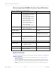
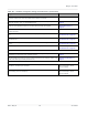
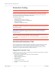
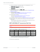
Table Of Contents
- Important Notice
- Safety and Hazards
- Limitation of Liability
- Contents
- List of Tables
- List of Figures
- 1: Introduction
- 2: Electrical Specifications
- 3: RF Specifications
- 4: Power
- 5: Software Interface
- 6: Mechanical and Environmental Specifica- tions
- 7: Regulatory Compliance and Industry Certifi- cations
- A: Antenna Specification
- B: Design Checklist
- C: Testing
- AT Command Entry Timing Requirement
- Acceptance Testing
- Certification Testing
- Production Testing
- Functional Production Test
- Quality Assurance Testing
- Suggested Testing Equipment
- Testing Assistance Provided by Lantronix, Inc.
- IOT/Operator Testing
- Extended AT Commands for Testing
- D: Packaging
- E: References
- F: Acronyms

Rev 5 May.21
62
41113694
Product
Technical
Specification
Recommended GNSS Antenna Specifications
Table A-2:
GNSS Antenna Requirements
Parameter Requirements Comments
Frequency
range
•
Wide-band GNSS:
1559–1606 MHz recommended
•
Narrow-band GPS:
1575.42 MHz ±2 MHz minimum
•
Narrow-band Galileo:
1575.42 MHz ±2 MHz minimum
•
Narrow-band BeiDou:
1561.098 MHz ±2 MHz minimum
•
Narrow-band GLONASS:
1601.72 MHz ±4.2 MHz minimum
•
Narrow-band QZSS:
1575.42 MHz ±2 MHz minimum
Field of view (FOV)
•
Omni-directional in azimuth
•
-45° to +90° in elevation
Polarization
(average Gv/Gh)
> 0 dB Vertical linear polarization is
sufficient.
Free space average
gain (Gv+Gh) over
FOV
> -6 dBi (preferably > -3 dBi) Gv and Gh are measured and
averaged over -45° to +90° in
elevation, and ±180° in azimuth.
Gain
•
Maximum gain and uniform coverage
in the high elevation angle and
zenith.
•
Gain in azimuth plane is not desired.
Average 3D gain > -5 dBi
Isolation between
GNSS and Ant1
•
All uplink bands: > 10 dB
•
To mitigate GNSS and LTE B13/B14
co-existence: > 20 dB
Typical VSWR < 2.5:1
Polarization Any other than LHCP (left-hand circular
polarized) is acceptable.
Antenna Tests
The following guidelines apply to the requirements described in Table A-1 on page 60 and
Table A-2 on page 62:
•
Perform electrical measurements at room temperature (+20°C to +26°C) unless
otherwise specified
•
For main and diversity path antennas, make sure the antennas (including contact
device, coaxial cable, connectors, and matching circuit with no more than six compo-
nents, if required) have nominal impedances of 50
Ω across supported frequency
bands.