
Technical Specs
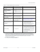
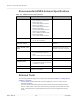
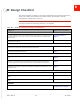
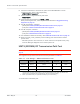
Table Of Contents
- Important Notice
- Safety and Hazards
- Limitation of Liability
- Contents
- List of Tables
- List of Figures
- 1: Introduction
- 2: Electrical Specifications
- 3: RF Specifications
- 4: Power
- 5: Software Interface
- 6: Mechanical and Environmental Specifica- tions
- 7: Regulatory Compliance and Industry Certifi- cations
- A: Antenna Specification
- B: Design Checklist
- C: Testing
- AT Command Entry Timing Requirement
- Acceptance Testing
- Certification Testing
- Production Testing
- Functional Production Test
- Quality Assurance Testing
- Suggested Testing Equipment
- Testing Assistance Provided by Lantronix, Inc.
- IOT/Operator Testing
- Extended AT Commands for Testing
- D: Packaging
- E: References
- F: Acronyms

Rev 5 May.21
61
41113694
Antenna Specification
Table A-1:
Antenna Requirements (Continued)
a
Parameter Requirements Comments
Radiation patterns of Ant1
and Ant2
Nominally Omni-directional
radiation pattern in azimuth plane.
Envelope correlation
coefficient between Ant1
and Ant2
•
< 0.5 on Rx bands below
960 MHz
•
< 0.2 on Rx bands above
1.4 GHz
Mean Effective Gain of
Ant1 and Ant2 (MEG1,
MEG2)
≥ -3 dBi
Ant1 and Ant2 Mean
Effective Gain Imbalance I
MEG1 / MEG2 I
< 2 dB for MIMO operation
< 6 dB for diversity operation
Maximum antenna gain
Must not exceed antenna gains
due to RF exposure and ERP/
EIRP limits, as listed in the
module’s FCC grant.
See Important Compliance Information for the
United States and Canada on page 57.
Isolation between Ant1 and
Ant2 (S21)
> 10 dB
•
If antennas can be moved, test all
positions for both antennas.
•
Make sure all other wireless devices
(Bluetooth or WLAN antennas, etc.) are
turned OFF to avoid interference.
Power handling
> 1 W on high bands
•
Measure power endurance over 4 hours
(estimated talk time) using a 1 W CW
signal— set the CW test signal frequency
to the middle of each supporting Tx band.
•
Visually inspect device to ensure there is
no damage to the antenna structure and
matching components.
•
VSWR/TIS/TRP measurements taken
before and after this test must show
similar results.
a. These worst-case VSWR figures for the transmitter bands may not guarantee RSE levels to be within regulatory limits. The
device alone meets all regulatory emissions limits when tested into a cabled (conducted) 50 ohm system. With antenna
designs with up to 2.5:1 VSWR or worse, the radiated emissions could exceed limits. The antenna system may need to be
tuned in order to meet the RSE limits as the complex match between the module and antenna can cause unwanted levels of
emissions. Tuning may include antenna pattern changes, phase/delay adjustment, passive component matching. Examples of
the application test limits would be included in FCC Part 22, Part 24 and Part 27,test case 4.2.2 for WCDMA
(ETSI EN 301 908-1), where applicable.
b. Ant1—Primary, Ant2—Secondary (Diversity/MIMO/GNSS)
c. Ant1—Primary, Ant2—Secondary (Diversity/GNSS)