
Technical Specs
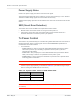
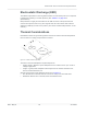
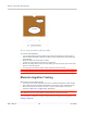
Table Of Contents
- Important Notice
- Safety and Hazards
- Limitation of Liability
- Contents
- List of Tables
- List of Figures
- 1: Introduction
- 2: Electrical Specifications
- 3: RF Specifications
- 4: Power
- 5: Software Interface
- 6: Mechanical and Environmental Specifica- tions
- 7: Regulatory Compliance and Industry Certifi- cations
- A: Antenna Specification
- B: Design Checklist
- C: Testing
- AT Command Entry Timing Requirement
- Acceptance Testing
- Certification Testing
- Production Testing
- Functional Production Test
- Quality Assurance Testing
- Suggested Testing Equipment
- Testing Assistance Provided by Lantronix, Inc.
- IOT/Operator Testing
- Extended AT Commands for Testing
- D: Packaging
- E: References
- F: Acronyms

Rev 5 May.21
56
41113694
Product
Technical
Specification
Figure 6-2: Copper Pad Location on Bottom Side of Module
To enhance heat dissipation:
•
It is recommended to add a heat sink that mounts the module to the main PCB or
metal chassis (a thermal compound or pads must be used between the module and
the heat sink).
•
Maximize airflow over/around the module.
•
Locate the module away from other hot components.
•
Module mounting holes must be used to attach (ground) the device to the main PCB
ground or a metal chassis.
•
You may also need active cooling to pull heat away from the module.
Note: Adequate dissipation of heat is necessary to ensure that the module functions properly.
Module Integration Testing
When testing your integration design:
•
Test to your worst case operating environment conditions (temperature and voltage)
•
Test using worst case operation (transmitter on 100% duty cycle, maximum power)
•
Monitor temperature at all shield locations. Attach thermocouples to the areas
indicated in Figure 6-1 on page 55 (RF, Baseband).
Note: Make sure that your system design provides sufficient cooling for the module.
(For acceptance, certification, quality, and production (including RF) test suggestions, see
Testing on page 66.)
RF
Baseband