
Technical Specs
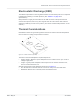
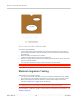

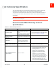
Table Of Contents
- Important Notice
- Safety and Hazards
- Limitation of Liability
- Contents
- List of Tables
- List of Figures
- 1: Introduction
- 2: Electrical Specifications
- 3: RF Specifications
- 4: Power
- 5: Software Interface
- 6: Mechanical and Environmental Specifica- tions
- 7: Regulatory Compliance and Industry Certifi- cations
- A: Antenna Specification
- B: Design Checklist
- C: Testing
- AT Command Entry Timing Requirement
- Acceptance Testing
- Certification Testing
- Production Testing
- Functional Production Test
- Quality Assurance Testing
- Suggested Testing Equipment
- Testing Assistance Provided by Lantronix, Inc.
- IOT/Operator Testing
- Extended AT Commands for Testing
- D: Packaging
- E: References
- F: Acronyms

Rev 5 May.21
55
41113694
Mechanical and Environmental Specifications
Electrostatic Discharge (ESD)
The OEM is responsible for ensuring that the EM7411 host interface pins are not exposed
to ESD during handling or normal operation. (See Table 6-1 on page 54 for
specifications.)
ESD protection is highly recommended for the SIM connector at the point where the
contacts are exposed, and for any other signals from the host interface that would be
subjected to ESD by the user of the product. (The device includes ESD protection on the
antenna.)
Thermal Considerations
Embedded modules can generate significant amounts of heat that must be dissipated in
the host device for safety and performance reasons.
Figure 6-1: Shield Locations (Top View)
The amount of thermal dissipation required depends on:
•
Supply voltage— Maximum power dissipation for the module can be up to 3.5 W at
voltage supply limits.
•
Usage— Typical power dissipation values depend on the location within the host,
amount of data transferred, etc.
Specific areas requiring heat dissipation are shown in Figure 6-2:
•
RF—Bottom face of module near RF connectors. Likely to be the hottest area.
•
Baseband—Bottom face of module, below the baseband area.
RF
Baseband