
Technical Specs
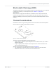
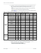
Table Of Contents
- Important Notice
- Safety and Hazards
- Limitation of Liability
- Contents
- List of Tables
- List of Figures
- 1: Introduction
- 2: Electrical Specifications
- 3: RF Specifications
- 4: Power
- 5: Software Interface
- 6: Mechanical and Environmental Specifica- tions
- 7: Regulatory Compliance and Industry Certifi- cations
- A: Antenna Specification
- B: Design Checklist
- C: Testing
- AT Command Entry Timing Requirement
- Acceptance Testing
- Certification Testing
- Production Testing
- Functional Production Test
- Quality Assurance Testing
- Suggested Testing Equipment
- Testing Assistance Provided by Lantronix, Inc.
- IOT/Operator Testing
- Extended AT Commands for Testing
- D: Packaging
- E: References
- F: Acronyms

Rev 5 May.21
52
41113694
Product
Technical
Specification
Power Supply Noise
Noise in the power supply can lead to noise in the RF signal.
The power supply ripple limit for the module is no more than 100 mVp-p 1 Hz to 100 kHz.
This limit includes voltage ripple due to transmitter burst activity.
Additional decoupling capacitors can be added to the main VCC line to filter noise into the
device.
SED (Smart Error Detection)
The module uses a form of SED to track premature modem resets.
•
Module tracks consecutive resets occurring soon after power-on.
•
After a sixth consecutive reset, the module waits in boot-and-hold mode for a
firmware download to resolve the power-cycle problem.
Tx Power Control
The module’s Tx power limit may be controlled using either SAR backoff AT commands or
the DPR (Dynamic power control) signal. Use the GPIOSARENABLE parameter for
!CUSTOM to choose the method:
•
AT commands:
·
!SARSTATEDFLT—Set (or report) the default SAR backoff state that the device
uses when it powers up. This setting is persistent across power cycles and
overrides any PRI setting.
·
!SARSTATE— Set (or report) the current SAR backoff state (override the default
state). This change in state is non-persistent across power cycles.
·
!SARBACKOFF— Set (or report) the maximum Tx power limit for a specific band/
technology/state combination.
Note: A customization is available to invert the DPR logic. (e.g. make DPR low = No SAR backoff)
•
Dynamic power control— The module’s firmware monitors DPR (pin 25) and adjusts
the RF Tx power appropriately, as detailed in Table 4-9. (This state change is equiv-
alent to issuing the !SARSTATE AT command.)
Table 4-9:
Dynamic Power Control of SAR Backoff State
DPR SAR backoff state
High
a
No SAR backof
Low Backoff 1
a.
DPR is pulled high by default.
Note: The host can implement an open collector drive for the DPR pin (if a 1.8 V-compatible drive is
not available).