
Technical Specs
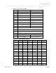
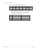
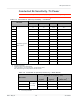
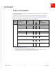
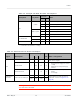
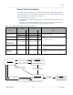

Table Of Contents
- Important Notice
- Safety and Hazards
- Limitation of Liability
- Contents
- List of Tables
- List of Figures
- 1: Introduction
- 2: Electrical Specifications
- 3: RF Specifications
- 4: Power
- 5: Software Interface
- 6: Mechanical and Environmental Specifica- tions
- 7: Regulatory Compliance and Industry Certifi- cations
- A: Antenna Specification
- B: Design Checklist
- C: Testing
- AT Command Entry Timing Requirement
- Acceptance Testing
- Certification Testing
- Production Testing
- Functional Production Test
- Quality Assurance Testing
- Suggested Testing Equipment
- Testing Assistance Provided by Lantronix, Inc.
- IOT/Operator Testing
- Extended AT Commands for Testing
- D: Packaging
- E: References
- F: Acronyms

Rev 5 May.21
49
41113694
Power
Power State Transitions
The module uses state machines to monitor supply voltage and operating temperature,
and notifies the host when critical threshold limits are exceeded. (See Table 4-5 for trigger
details and Figure 4-1 for state machine behavior.)
Power state transitions may occur:
•
Automatically, when critical supply voltage or module temperature trigger levels are
encountered.
•
Under host control, using available AT commands in response to user choices (for
example, opting to switch to airplane mode) or operating conditions.
Table 4-5: Power State Transition Trigger Levels
Transition
Voltage
Temperature
a
Notes
Trigger V Trigger °C
Normal to Low Power
VOLT_HI_CRIT 4.4 TEMP_LO_CRIT -45
•
RF activity suspended
VOLT_LO_CRIT 3.135 TEMP_HI_CRIT 110
Low Power to Normal VOLT_HI_NORM 4.3 TEMP_LO_NORM -30
•
RF activity resumed
Low Power to Normal
or
Remain in Normal
(Remove warnings)
VOLT_LO_NORM
3.3
TEMP_HI_NORM
70
Normal (Issue warning)
VOLT_LO_WARN
3.2
TEMP_HI_WARN
85
•
In the TEMP_HI_WARN state, the module may
have reduced performance (Class B temperature
range).
Power off/on
(Host-initiated)
-
-
-
-
•
Power off recommended when supply voltage or
module operating temperature is critically low or
high.
a.
Module-reported temperatures at the printed circuit board.
Normal mode
current_vcc < VOLT_LO_WARN
current_temp > TEMP_HI_WARN
current_vcc > VOLT_LO_NORM
current_temp < TEMP_HI_NORM
Normal mode
Low supply voltage warning
or
High temperature warning
current_vcc > VOLT_LO_NORM
current_temp <= TEMP_HI_NORM
current_vcc < VOLT_LO_CRIT
current_temp > TEMP_HI_CRIT
current_vcc > VOLT_HI_CRIT
current_temp < TEMP_LO_CRIT
current_vcc < VOLT_HI_NORM
current_temp > TEMP_LO_NORM
Low power mode
Handled by Power
State state machine.
(Manual transition)
Host deasserts
Full_Card_Power_Off#
Figure 4-1: Voltage/Temperature Monitoring State Machines
Off mode
Handled by Power
State state machine