
Technical Specs
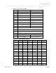
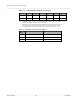
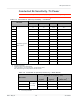
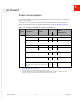
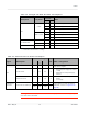
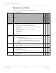

Table Of Contents
- Important Notice
- Safety and Hazards
- Limitation of Liability
- Contents
- List of Tables
- List of Figures
- 1: Introduction
- 2: Electrical Specifications
- 3: RF Specifications
- 4: Power
- 5: Software Interface
- 6: Mechanical and Environmental Specifica- tions
- 7: Regulatory Compliance and Industry Certifi- cations
- A: Antenna Specification
- B: Design Checklist
- C: Testing
- AT Command Entry Timing Requirement
- Acceptance Testing
- Certification Testing
- Production Testing
- Functional Production Test
- Quality Assurance Testing
- Suggested Testing Equipment
- Testing Assistance Provided by Lantronix, Inc.
- IOT/Operator Testing
- Extended AT Commands for Testing
- D: Packaging
- E: References
- F: Acronyms

Rev 5 May.21
48
41113694
Product
Technical
Specification
Module Power States
The module has five power states, as described in Table 4-4.
Table 4-4:
Module Power States
State
Details
Host
is powered
USB
interface
active
Radio
enabled
Normal
(Default
state)
•
Module is active
•
Default state. Occurs when VCC is first applied, Full_Card_Power_Off# is
deasserted (pulled high), and W_DISABLE# is deasserted
•
Module is capable of placing/receiving calls, or establishing data connections on the
wireless network
•
Current consumption is affected by several factors, including:
•
Radio band being used
•
Transmit power
•
Receive gain settings
•
Data rate
✔ ✔ ✔
Low power
(‘Airplane
mode’)
•
Module is active
•
Module enters this state:
•
Under host interface control:
·
Host issues AT+CFUN=0 ([1] AT Command Set for User Equipment (UE)
(Release 6) (Doc# 3GPP TS 27.007))), or
·
Host asserts W_DISABLE#, after AT!PCOFFEN=0 has been issued.
•
Automatically, when critical temperature or voltage trigger limits have been
reached))
✔ ✔
✘
Sleep
•
Normal state of module between calls or data connections
•
Module cycles between wake (polling the network) and sleep, at network provider-
determined interval.
✔
✘
a
✘
Off
•
Host keeps module powered off by asserting Full_Card_Power_Off# (signal pulled
low or left floating)
•
Module draws minimal current
•
See Full_Card_Power_Off# and RESET# on page 32 for more information.
✔
✘
a
✘
Disconnected
•
Host power source is disconnected from the module and all voltages associated with
the module are at 0 V.
✘
✘
b
✘
a. USB interface is suspended
b. USB interface is disconnected