
Technical Specs
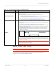
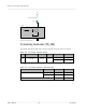
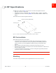
Table Of Contents
- Important Notice
- Safety and Hazards
- Limitation of Liability
- Contents
- List of Tables
- List of Figures
- 1: Introduction
- 2: Electrical Specifications
- 3: RF Specifications
- 4: Power
- 5: Software Interface
- 6: Mechanical and Environmental Specifica- tions
- 7: Regulatory Compliance and Industry Certifi- cations
- A: Antenna Specification
- B: Design Checklist
- C: Testing
- AT Command Entry Timing Requirement
- Acceptance Testing
- Certification Testing
- Production Testing
- Functional Production Test
- Quality Assurance Testing
- Suggested Testing Equipment
- Testing Assistance Provided by Lantronix, Inc.
- IOT/Operator Testing
- Extended AT Commands for Testing
- D: Packaging
- E: References
- F: Acronyms

Rev 5 May.21
37
41113694
RF Specifications
Antenna and Cabling
When selecting the antenna and cable, it is critical to RF performance to match antenna
gain and cable loss.
Note: For detailed electrical performance criteria, see Appendix A: Antenna Specification on
page 60.
Choosing the Correct Antenna and Cabling
When matching antennas and cabling:
•
The antenna (and associated circuitry) should have a nominal impedance of 50 Ω
with a return loss of better than 10 dB across each frequency band of operation.
•
The system gain value affects both radiated power and regulatory (FCC, IC, CE, etc.)
test results.
Designing Custom Antennas
Consider the following points when designing custom antennas:
•
A skilled RF engineer should do the development to ensure that the RF performance
is maintained.
•
If both UMTS and CDMA modules will be installed in the same platform, you may
want to develop separate antennas for maximum performance.
Determining the Antenna’s Location
When deciding where to put the antennas:
•
Antenna location may affect RF performance. Although the module is shielded to
prevent interference in most applications, the placement of the antenna is still very
important—if the host device is insufficiently shielded, high levels of broadband or
spurious noise can degrade the module’s performance.
•
Connecting cables between the module and the antenna must have 50 Ω impedance.
If the impedance of the module is mismatched, RF performance is reduced signifi-
cantly.
•
Antenna cables should be routed, if possible, away from noise sources (switching
power supplies, LCD assemblies, etc.). If the cables are near the noise sources, the
noise may be coupled into the RF cable and into the antenna. See Interference from
Other Wireless Devices on page 38.
Disabling the Diversity Antenna
Certification testing of a device with an integrated EM7411 may require the module’s main
and diversity antennas to be tested separately.
To facilitate this testing, receive diversity can be enabled/disabled using AT commands:
•
!RXDEN—Used to enable/disable diversity for single-cell call (no carrier aggre-
gation).
•
!LTERXCONTROL— Used to enable/disable paths (in carrier aggregation scenarios)
after a call is set up.